Continue to Site

Welcome to EDAboard.com

Welcome to our site! EDAboard.com is an international Electronics Discussion Forum focused on EDA software, circuits, schematics, books, theory, papers, asic, pld, 8051, DSP, Network, RF, Analog Design, PCB, Service Manuals... and a whole lot more! To participate you need to register. Registration is free. Click here to register now.

Discrete frequency to voltage converter

Status
Not open for further replies.

neazoi

Advanced Member level 6
Joined
Jan 5, 2008
Messages
4,122
Helped
13
Reputation
26
Reaction score
15
Trophy points
1,318
Location
Greece
Activity points
36,951
Gi I am thinking of these old analogue transceivers/receivers, with analogue scales. Some of these are accurate to the KHz, but not more accurate than that.
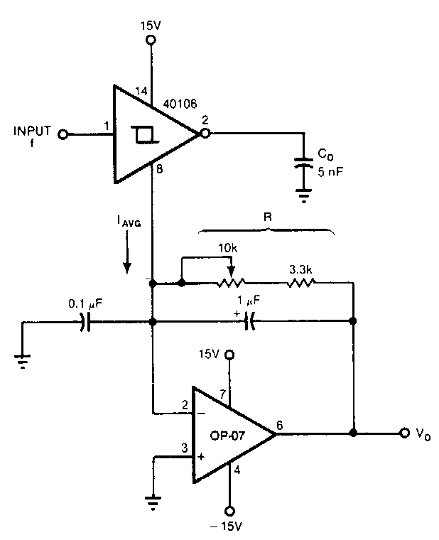
I am trying to find a circuit to measure variations in frequency (say a few Hz to 1KHz or so) and use an analogue meter as a display. This will increase the accuracy reading of these boatanchors.

A simple one is here https://www.redcircuits.com/Page147.htm but I am thinking how such a thing can be made discrete.
 

High-pass filter followed by peak detector. Experimentation and adjustment is needed to obtain desired operation. I made the load 20 Kohm simply because a typical analog VOM spec is 20K per volt.

To change frequency range, switch in different capacitors (similar to the project at your link).

As an option you can feed the incoming signal to a class A amplifier, in order to amplify its voltage. This may improve linearity of response at the peak detector.

freq-to-V conv 10-100 Hz CR hi-pass filter then peak detector.png
 
  • Like
Reactions: neazoi

    neazoi

    Points: 2
    Helpful Answer Positive Rating
I think Neazoi is looking for a few KHz in tens of MHz, not a 10:1 frequency range!

A trick used a long time ago was to create a comb spectrum with peaks say 100KHz apart and feed it to the input of a PLL. The reference frequency was the LO of the receiver/transceiver (possibly through a divider). It didn't measure frequency as such but it did indicate how close and in which direction the nearest peak in the comb was. So for 100KHz peaks it would give an analog meter reading of -50KHz to +50KHz with the needle swinging end to end of the scale as the LO was tuned through each 100KHz interval regardless of what the absolute frequency was. The comb generator was of course stablized by a quartz crystal.

These days a very simple and accurate analog tuning meter can be made using a simple MCU but I appreciate you are trying not to do that. If you decided to go digital, all you need to do is measure absolute frequency then use the last one or two digits of the measurement to deflect a moving coil meter.

Brian.
 
  • Like
Reactions: neazoi

    neazoi

    Points: 2
    Helpful Answer Positive Rating
Meanwhile I have found another circuit that I do not know how well it will work until I test it. What is the purpose of these emitter disconnected transistors?

I am looking something in the audio range. Because you know these vintage transceivers with analogue dials, had crystal calibrators so that you could calibrate the dial. The ft-301 (analogue dial version) for example was quite accurate to 1khz within 50KHz when re-calibrated with it's 25KHz crystal marker generator.

But I am looking something to measure the frequency more accurately within a few KHz, then like you said in the comb generator situation, reset the counter and measure the next dozen of khz. Since it has to match the technology and display style of the era, I do not like a digital counter with LCD.

Another approach would be a led (not 7-segment) BDC counter, but it will be a bit hadrer to add the values of the LEDs.
I find the meter idea quite good looking and neat and if the range of the frequency capability to measure is low, the reading will be more accurate.

The simplest way I can think of, is to use a circuit like the one attached, and then use the 25KHz crystal callibrator of the radio, periodically switched on, and measure the beat tone in the audio range with this circuit.
Problem is that this will be able to measure only within 3KHz (crystal filter) or so near the marker frequency, the rest of the dial cannot be measured. So in this approach a marker generator of say 1KHz is needed and then measure the frequency with this analogue meter in the 1-2KHz span. How on earth I can produce a 1KHz marker generator on HF (prefferably in discrete if possible), I have no idea?
 

Attachments

  • 0-200kHz_Analog_Frequency_Meter.gif
    0-200kHz_Analog_Frequency_Meter.gif
    16.2 KB · Views: 198
Last edited:

The circuit is a single stage amplifier followed by two charge pump stages but I'm not sure it would do what you want anyway. Being able to tell how far off the tuning scale is from real frequency by measuring a beat tone means you have to tune to the calibrator signal, note the discrepancy then add/subtract it from the dial frequency when you are back on the station you want. A more practical solution would be a 'fine tune' control that let you adjust to zero beat at the calibrator frequency, then the dial would always be as accurate as possible, at least within close frequency range.

I wasn't suggesting a digital readout, I meant to use a moving coil meter but generate the voltage it measured digitally.

A radical alternative that suits all the requirements but would take some work is here:
Look at the Swan transceiver!
There is also somewhere on the internet a similar article where a vintage rotary tuning dial is replaced with an almost identical one using an oled or color LCD. The appearance is the same but the scale is of course based on reading the frequency using a digital counter so it is very accurate.

Brian.
 

    neazoi

    Points: 2
    Helpful Answer Positive Rating
Oh man... I can't imagine how many ghost signals will it introduce inside this receiver. But it is a neat graphic indeed!

Yes the solution I proposed seems to me a bit impractical.

But This project fired another one. Look at the comb generator of the pdf https://worldradiohistory.com/Archive-DX/Ham Radio/80s/Ham-Radio-198501.pdf and look at this circuit https://www.ve3oat.ca/dividercircuit.html

I wonder how can I introduce the 1KHz markers as well at an even lower level?
A simple way I think is to remove the switch and duplicate the output circuit presented in the website, one for each marker frequency and then combine them at the output and the level of each one will be controlled by a trimmer. Will that work?

And how I can derive a 1MHz input signal out of a 10MHz crystal (which chip to use)

This would make a nice marker generator.
 

The first link is to a comb filter, not a comb generator! A comb generator is essentially a harmonic generator that attempts to keep the harmonics at a constant level.

The second link shows a chain of divide by 10 circuits so if you wanted to start with 10MHz instead of 1MHz, just add an extra stage and use a 10MHz source. TTL (74xx devices) are quite old now but they still work well at producing harmonic rich square waves. If you use 'S', 'F' or 'LS' it might work better but don't use CMOS variants as these tend to have 'softer' edges which restricts their higher frequency content.

Be aware that the closer the harmonics are to each other, the greater the chances are that you will pick the wrong one. For example, if you have a marker at 1KHz intervals you could easily mistake the 10.000MHz one for the 10.001MHz one! I would recommend no closer than about 5KHz and ideally 10KHz but it depends on how accurate you know the tuning to be beforehand.

Brian.
 

    neazoi

    Points: 2
    Helpful Answer Positive Rating
I posted the wrong link.
Here is the correct https://worldradiohistory.com/Archive-DX/Ham Radio/80s/Ham-Radio-198601.pdf
The website one is derived from the PDF one.

So I am thinking of combining the outputs but first buffer them with separate dual gates (74S00) like the one shown in the diagram. An output pot for each one will be used to set the desired level of each one.
Will that work?

Also I do not have the LS90 chip, what other chips can i use? I have hct4060 for example
 
Last edited:

I doubt using pots would work, you would need to sum their outputs in a very high speed amplifier. The method used in the original article is better.
Note that there is a design error in the schematic, it wouldn't stop it working but purists would frown at it! The 1MHz marker switch should be a change-over type with the 'off' position being tied to VCC. Leaving a gate input open might work with old 74xx ICs because in most cases the pin defaults to a high logic state but it certainly wouldn't work with the equivalent CMOS types.

The HCT4060 could be used but your markers wouldn't be at multiples of 10KHz because it divides by 2 at each stage instead of 10. An alternative in current production might be the 74HC160 but you would have to wire the preset pins to load '6' so it divided by 10 instead of 16.

Brian.


https://www.analog.com/media/en/technical-documentation/data-sheets/AD654.pdf

Another approach, quite accurate with good resolution, use a low end processor, crystal clock, and
measure freq. Use that result and set the duty cycle of a 16 bit PWM, also onchip, with a R-C LPF to
yield V. The chip should be powered by a precision Vref, say 5V, to get accurate translation. This
approach I think could approach .1% accuracy. Would look something like this (single chip) -

1601770838822.png


Regards, Dana.
 
Last edited:

Pure analog solution for å few orders of magnitude frequency range might be a logarythmic integrator (circuit well known in sensor readout before digital long counters times).

There were two kinds of such circuit:
Goodyear implementation and Cooke−Yarboroug.
 

Status
Not open for further replies.

Similar threads

Part and Inventory Search

Welcome to EDABoard.com

Sponsor

Back
Top