Continue to Site

Welcome to EDAboard.com

Welcome to our site! EDAboard.com is an international Electronics Discussion Forum focused on EDA software, circuits, schematics, books, theory, papers, asic, pld, 8051, DSP, Network, RF, Analog Design, PCB, Service Manuals... and a whole lot more! To participate you need to register. Registration is free. Click here to register now.

Discrete components, low distortion, variable with a single resistor, audio oscillator

Status
Not open for further replies.

neazoi

Advanced Member level 6
Joined
Jan 5, 2008
Messages
4,119
Helped
13
Reputation
26
Reaction score
15
Trophy points
1,318
Location
Greece
Activity points
36,918
Hi,
I would like to built a simple audio oscillator in the 480Hz-2700Hz range with the next requirements:

1. Discrete components
2. Variable in the 480Hz-2700Hz range
3. Frequency to be varied with a single variable resistor preferably, not a stereo potentiometer or other dual controls, if possible
4. Single range, i.e not switching to be required for the whole 480-2700Hz
4. Low distortion, so as to avoid harmonics in the passband

Can you propose me any circuits, or present any simulations to try?

Thank you
 

sine wave? square wave? triangle wave? Low distortion: 1%? 0.00001%?

Hey, here's an idea:

1) Go to google.com , bing.com, or some other search engine.
2) Type: "Audio oscillator circuit".
3) Hit "ENTER".
3) Gasp in amazement at the number of resources available.
 

sine wave? square wave? triangle wave? Low distortion: 1%? 0.00001%?

Hey, here's an idea:

1) Go to google.com , bing.com, or some other search engine.
2) Type: "Audio oscillator circuit".
3) Hit "ENTER".
3) Gasp in amazement at the number of resources available.

Amazing answer! Thank you I will do so...
 

I presume this has to be a sine wave or the 'avoid harmonics in the passband' wouldn't make sense.

I think the only practical solution would be a Wien bridge oscillator but for low distortion you need a dual gang resistor (ideally linear so not a 'stereo' control).

The only other solution I can think of is to generate a square wave first but at four times the frequency you want, divide it by two in a bistable circuit to ensure it has equal mark-space (a 'perfect' square wave), the divide by two again but use constant current sources to alternately charge and discharge a capacitor, this give a 'perfect' triangle wave at the frequency you want. Finally, use a non-linear amplifier or clamp to progressively compress the peaks of the triangle wave to make it close to a sine shape. This is the technique used in some 'universal' wave generators because it produces simultaneous square, triangle and sine outputs.

It isn't simple though.

Brian.
 

    neazoi

    Points: 2
    Helpful Answer Positive Rating
I presume this has to be a sine wave or the 'avoid harmonics in the passband' wouldn't make sense.

I think the only practical solution would be a Wien bridge oscillator but for low distortion you need a dual gang resistor (ideally linear so not a 'stereo' control).

The only other solution I can think of is to generate a square wave first but at four times the frequency you want, divide it by two in a bistable circuit to ensure it has equal mark-space (a 'perfect' square wave), the divide by two again but use constant current sources to alternately charge and discharge a capacitor, this give a 'perfect' triangle wave at the frequency you want. Finally, use a non-linear amplifier or clamp to progressively compress the peaks of the triangle wave to make it close to a sine shape. This is the technique used in some 'universal' wave generators because it produces simultaneous square, triangle and sine outputs.

It isn't simple though.

Brian.

Indeed it sounds too complicated.
I was thinking that one could also use a variable crystal oscillator on HF (vxo) and mix it down to audio. Then use a simple LPF to keep only the audio.
This should work in theory and should provide a very clean sinewave.

I am not sure if I will go that way, I still investigate oscillators such as the one attached. A forum member had replied this a few months ago if I remember well. But as far as I understand it uses a dual potentiometer isn't it?

So maybe the VXO solution is the best and the simplest?
 

Attachments

  • wienAFosc.PNG
    wienAFosc.PNG
    95.6 KB · Views: 110

R7 and R8 have to be ganged in that design. It is a Wien bridge with a JFET as active gain controller.

Yes, you can mix a high frequency crystal oscillator with a VCO but it may not be as simple as it sounds. Frequency stability is the main issue, you would have a high frequency RF generator with frequency set by a potentiometer, that sound like a recipe for drift with temperature. There is also the point that unless you keep both oscillator levels well within the mixer dynamic range it will distort the output waveform and you have to be careful what frequencies you use if you are mixing them to get a low frequency result. Without sufficient isolation between the signals you might get injection locking when they are only a few hundred Hz apart.

Brian.
 

Without sufficient isolation between the signals you might get injection locking when they are only a few hundred Hz apart.
This is in fact what I was thinking the most.
You see you can have two crystal oscillators, the one fixed say at 10MHz the other variable (vxo) 1-3KHz (crystal pulling), but you then have to have a network at the output to isolate their outputs.
It more reminds me of a 2-tone generator like the one presented in this page Inband IMD Immunity Testing (ab4oj.com) but you can also find such designs on the net. These use a bridge at the output that isolates the two closely-operated oscillators. Perhaps I should search more for a two-tone generator circuits, if I want to go that way.

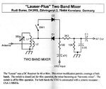
But there are some other ideas, for example one can have 2 oscillators, one of them operating at half the frequency and mix it's harmonics with the other. This should still produce an audible done from one of the first oscillator harmonics, mixed with the main signal of the other oscillator without interlocking. A simple audio LPF after the mixing of these oscillators should be enough for keeping only the audio tone. See for example the polyakov mixer attached. The 2 signals should not interlock.
What do you think?
 

Attachments

  • Beat_Crystal_Freq_Meter_W5JSN.gif
    Beat_Crystal_Freq_Meter_W5JSN.gif
    16.3 KB · Views: 124
  • PolyakovPlus2133.jpg
    PolyakovPlus2133.jpg
    245.8 KB · Views: 73
Last edited:

This is one of those times, when one really misses the XR2206.
 

XR2206 was really useful, it used a clamp circuit to 'round off' the triangle wave as I described earlier. Not perfect, but acceptable.
I don't think it would be practical to construct an XR2206 out of discrete components though.

Brian.
 

The retro project was needed to use discrete components. Vacuum tubes?
I was thinking about transistors only.
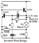
I have tried this circuit but I could not keep the level constant at the edges of the frequency spectrum. I think it has to do with the incandescent properties. I only had a 500r stereo pot so I increased the caps to 1uF. Anyway I a not very satisfied and after all it uses a stereo pot.

Now I could replace the stereo pot with two LDRs, driven with leds, which in turn would be driven by a mono potentiometer. Even if ldrs are not very matched, it should provide acceptable distortion I think. I believe that to some point the ldrs couls be replaced by a set of transistors used as variable resistance devices.

In that sense, maybe a phase shift oscillator can be used, but could it provide a good sinewave if set for low gain?

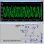
I have not yet tried the simulated circuit above (a bit more complex)

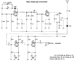
The RF mixers idea, driving a polyakov mixer could be derived from this circuit https://www.qsl.net/dl1gsj/html/qrssrx30.html
 

Attachments

  • invwein.gif
    invwein.gif
    7.7 KB · Views: 67

A Triangle wave is only a few % different to a sine wave - so make a triangle wave generator and filter it - too easy ...
 

A Triangle wave is only a few % different to a sine wave - so make a triangle wave generator and filter it - too easy ...
A filtered triangle wave generator will work if the frequency is not changed because then all the RC filters would also need changing.
You might as well make a Wien Bridge or Phase shift oscillator that does not need filtering.
 

When designing the XR2206 the makers looked for the most efficient method to create a sinewave. They decided on the diode shaping technique. I imagine it's because the effect is independent of frequency.

Once you have a regulated triangle wave, a pair of zener diodes back-to-back is sufficient to round the peaks so you get a semblance of a sine. (If you wish you can shape it further by adding another set of diodes with a different volt rating.)

The rightmost XY figure plots the output against a pure sine. The aim is to carefully adjust the potentiometer until the trace is a straight line, or as close as you can get.

back-to-back zener diodes shape triangle wave to quasi-sine.png
 

    neazoi

    Points: 2
    Helpful Answer Positive Rating
When designing the XR2206 the makers looked for the most efficient method to create a sinewave. They decided on the diode shaping technique. I imagine it's because the effect is independent of frequency.

Once you have a regulated triangle wave, a pair of zener diodes back-to-back is sufficient to round the peaks so you get a semblance of a sine. (If you wish you can shape it further by adding another set of diodes with a different volt rating.)

The rightmost XY figure plots the output against a pure sine. The aim is to carefully adjust the potentiometer until the trace is a straight line, or as close as you can get.

View attachment 167880

The output is by far not a sinewave though. Maybe more like something that approximates a sinewave only...
I think I am going to give a try to the post #5 circuit, as my options start to decrease. I will let you know about the results.
I will also give a try to this transistor used as a resistance device thing. Maybe for the limited range I am interested in, this is a very viable solution.
 

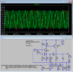
Ok this circuit worked. The BJTs were more critical, I could not use 2n2222, it needed to be bc547. Now, at 12v the gain is a bit more so there is some clipping at the bottom of the sine. I think the ALC does not work correctly, cause even if I remove C6 I see no signal change. However if O remove the jfet, there is no oscillation anymore

Update: I replaced R10 with a higher value resistor (33k) and the distortion (and the signal level a bit) went down

Also I would like to avoid 1uF capacitors (can I use electrolytics?) and use 470nF maximum. What resistors I need to increase for this change?
 

Attachments

  • wienAFosc.PNG
    wienAFosc.PNG
    95.6 KB · Views: 70
Last edited:

A filtered triangle wave generator will work if the frequency is not changed because then all the RC filters would also need changing.

When you feed the output of a triangle generator to a classical difference amplifier (long-tailed pair) you get a pretty good sine wave with a THD of lower than 1% - indpendent on frequency (because this is not a filtering but a wave shape).
However, it is important that the triangle amplitude has a certain (fixed) value of ap.p 60mVolts.
 

A ganged potentiometer will vary the freq and the R's of the filter to keep the filtering in the same ratio ... making it easy to produce a sine from a triangle .... you can do similar with digital pots ...
 

Back in my undergrad circuit design course, we were tasked with making a sine wave generator whose output amplitude was independent of frequency, without special ICs. Most students took the approach of using resistor/diode networks to shape a triangle wave into a sine wave. But one student took the approach of creating a switched capacitor filter whose clock frequency tracked with the output frequency. Results were very nice, assuming you didn't adjust the frequency faster than his PLL could track.
 

My very low distortion variable frequency sinewave circuit uses a CD4018 counter to produce a stepped levels "sinewave" that is also filtered with a switched-capacitor Butterworth lowpass filter IC. The clock tor the counter and for the switched capacitor filter is the same so it adjusts the frequency with a single pot with perfect immediate tracking..

The Wien Bridge oscillator with the obsolete Jfet (others are still available) uses a dual linear pot. Its 1uF capacitors are used for low frequencies that you do not need, use 330nF instead.
Transistors have a wide range of current gain and a high output resistance, use an opamp instead.
The AGC does not work if the diode is backwards.
 

Attachments

  • Wien bridge oscillator with FET AGC.PNG
    Wien bridge oscillator with FET AGC.PNG
    22.8 KB · Views: 116

Status
Not open for further replies.

Similar threads

Part and Inventory Search

Welcome to EDABoard.com

Sponsor

Back
Top