Continue to Site

Welcome to EDAboard.com

Welcome to our site! EDAboard.com is an international Electronics Discussion Forum focused on EDA software, circuits, schematics, books, theory, papers, asic, pld, 8051, DSP, Network, RF, Analog Design, PCB, Service Manuals... and a whole lot more! To participate you need to register. Registration is free. Click here to register now.

Discovery of electromagnetic shielding

Status
Not open for further replies.

Kajunbee

Advanced Member level 1
Joined
Nov 5, 2016
Messages
455
Helped
93
Reputation
186
Reaction score
105
Trophy points
1,323
Activity points
5,108
This is one of Faradays experiments that Joseph Henry replicated. Faraday said that interposing a plate of copper or zinc did not show any shielding effect, But Henry’s experiments showed to the contrary. Can anyone see a reason why interposing a zinc plate would not deflect the galvanometer, yet the needle inside the magnetizing spiral is strongly magnetized. If I’m understanding the setup correctly current is induced in both secondary, but current is in opposition in galvanometer. Also the magnetizing spiral consist of two coils which I’m only assuming are opposing.
The main difference between Faraday and Henry’s experiments was that Faraday relied on motion. I believe he was raising and lowering battery plates. Whereas Henry was using mercury to deliver current to his coils. Applying full battery voltage instead increasing slowly.
--- Updated ---

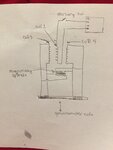
I realize the wording is difficult to follow. This is the setup to the best of my knowledge.
--- Updated ---

Drawing.
--- Updated ---

I did not include it in drawing but there would be a zinc plate between the primary and one of the secondary’s. If there was shielding this would cause and imbalance and deflection on galvanometer. If I understand the setup correctly current flows through spiral and galvanometer in opposition. I can’t think of any scenario where the needle gets magnetized but no deflection of galvanometer.
--- Updated ---

I’m not sure if this is a clue, but I believe someone might be able to answer. In the previous paragraph 46 he says that if the body is placed in the circuit that zinc plate will almost completely neutralize the shocks. Notice he says almost, not completely. But if the galvanometer is placed across the secondary there is no screening effect. So it seems to be related to the resistance or impedance of the load.
--- Updated ---

The experiment on page 46 was a different setup than one in drawing. There was only one primary and secondary.
 

Attachments

  • 0411FF63-0EF4-453E-985B-353763DF2C2C.png
    0411FF63-0EF4-453E-985B-353763DF2C2C.png
    2.3 MB · Views: 113
  • 93EE8D4B-1F28-4E14-9717-2D1D85E6C670.jpeg
    93EE8D4B-1F28-4E14-9717-2D1D85E6C670.jpeg
    740.6 KB · Views: 114
Last edited:

I am unable to follow the experimental setup.

What is the device (shown in the drawing) supposed to detect or measure?

Normal galvanometers have either a moving coil or a moving magnet. The deflection depends on the current.

What you have shown appears to be a transformer. One set of coil is fed from a power source and there are a set of several coupled coils. The sense of winding in the different coils shall be important.

You can simplify the experiment and revise the question.
 

Metallic plates could act as shorting
windings, lossy windings, lossy core
or a second core; perhaps that is the
point. A couple of metals doesn't
begin to cover it. Couple of geometries
neither. Means and frequencies of
excitation....
 

    Kajunbee

    Points: 2
    Helpful Answer Positive Rating
The purpose of the experiment was to detect whether non-ferrous materials (copper,zinc etc.) could shield electromagnetic waves. I found and explanation why Faraday and Henry had different results. I’m not clear on explanation so I will provide a link.

The magnetizing spiral (coils) is two equal length wires wound together on a hollow piece of straw. A iron needle was then inserted into the straw. Current flowing in these two coils exactly canceled each other and would not magnetize the needle.

The galvanometer was the same principle. A pair of wires wound on a common frame. Induced currents would cancel each other. Therefore no deflection of the needle.

A metal plate was inserted between let’s say #1 and #4. If that metal had any shielding effect it would cause and imbalance in current. This imbalance would be detected by galvanometer and the needle would magnetize.

The drawing is the exact setup they used. The center coil #1 would induce voltage in 3 and 4. These were just coils placed next to each other. The switch Henry used was a wire inserted into cup of mercury and source was galvanic cell.
--- Updated ---

The explanation is second full paragraph.
 

Attachments

  • D09D7959-690D-43F0-8A51-5086834E274E.png
    D09D7959-690D-43F0-8A51-5086834E274E.png
    1.1 MB · Views: 91
Last edited:

Let's say, the text snippet and drawing are a rather undescriptive way to show the problem.

It's completely clear for RF experts that non-ferrous materials shield electromagnetic waves respectively AC magnetic fields, the shielding effect is related to skin depth at the specific frequency. Thus it's almost meaningless to discuss the question without referring to actual signal frequency. A signal that can be detected with a galvanometer will be probably not effectively shielded by a non-ferromagnetic metal sheet.
 
Last edited:

    Kajunbee

    Points: 2
    Helpful Answer Positive Rating
FVM, the voltage was supplied by the sudden making and breaking of a galvanic current. I understand why copper shields high frequency. My confusion is why the needle was magnetized in the experiment.

He states that when plate was interposed there was no deflection. This would indicate no shielding effect. The induced current in both secondary’s was equal so they cancel each other out in galvanometer and also the magnetizing spiral.

He then says that that the needle in the magnetizing spiral was strongly magnetic. This would indicate that the plate did provide shielding and that the imbalanced currents allowed the needle to be magnetized.

These are polar opposite results in the same test. So either I’m not understanding the experiment correctly or he me a mistake in this experiment.
 

Can you give a link to the full experiment description, particularly where a discrepancy between Faraday and Henry is stated?
 

Give me a minute.
--- Updated ---

Beginning on pg. 162 section 2, titled “ on apparently two kinds of electrodynamic induction.https://ia800302.us.archive.org/27/items/scientificwriti03henrgoog/scientificwriti03henrgoog.pdf
--- Updated ---

C6A50F65-19E1-4F74-A5B6-BD89433034E7.png

This is a description of the same experiment in Faradays own words.
 
Last edited:

Today we know well about electromagnetic shielding.

As you have pointed out, both conducting materials (say a copper or silver plate) or a magnetic material (a sheet of iron or related material) can shield electromagnetic waves. The extent of shielding depends on many factors, one of them is the frequency of the electromagnetic radiation. If you want a perfect shield, get a superconductor (the Meissner effect).

Gamma rays are electromagnetic radiations but are hard to shield (also consider cosmic rays). Also consider very low frequency radio communication that are not easily blocked. In between lies the visible radiation (a very small range indeed) that can be blocked by a sheet of paper. A sheet of black paper is neither conducting nor magnetic to any significant extent.
 

    Kajunbee

    Points: 2
    Helpful Answer Positive Rating
Metallic plates could act as shorting
windings, lossy windings, lossy core
or a second core; perhaps that is the
point. A couple of metals doesn't
begin to cover it. Couple of geometries
neither. Means and frequencies of
excitation....

Although I don’t understand why, but when a galvanometer is in the circuit there is no shielding effect. But when Henry holds the secondary wires in his hands there is a noticeable shielding. The shocks are very feeble.
For clarity I am speaking about his other experiments where a single coil galvanometer is used.

This comment is related to the experiment in my crude drawing. Since the currents in the galvanometer coil and spiral are opposing this means they are non-inductive , correct? If so then current is only limited by the circuits resistance. Much the same as when Henry holds the wire in his hands. So there should be a noticeable shielding effect and therefore and imbalance current between coil #3 and #4. Does this sound reasonable so far.
--- Updated ---


I found these photos of Henry’s galvanometers. Each had a different number of windings. One for measuring intensity and the other for measuring a current of considerable quantity.
 
Last edited:

Since the currents in the galvanometer coil and spiral are opposing this means they are non-inductive , correct?

Not quite; it is a good approximation at large distances. As you know, one of the problems in common transformers is that the primary are secondary are not close enough. This lack of closeness causes flux leakage which is one of the sources of losses.

To be truly non-inductive, you must place the wires side by side without any gap. Then the fields everywhere will get canceled.
 

    Kajunbee

    Points: 2
    Helpful Answer Positive Rating
Status
Not open for further replies.

Similar threads

Part and Inventory Search

Welcome to EDABoard.com

Sponsor

Back
Top