mersault
Member level 2
Hello,
I'm trying to make a dipole antenna for UHF (433 MHz). I have a 50 Ohm unbalanced output so I need to balance it and do an impedance matching to get the best performance possible. I bought some Minicircuits' ADT1.5-1 (https://www.minicircuits.com/pdfs/ADT1.5-1.pdf) to do the job.
I made a PCB, soldered the transformer and the legs of the dipole obtaining something like this.
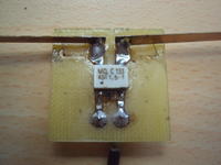
Lengths of the legs were calculated for the frequency given (about 16.5 cm)
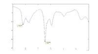
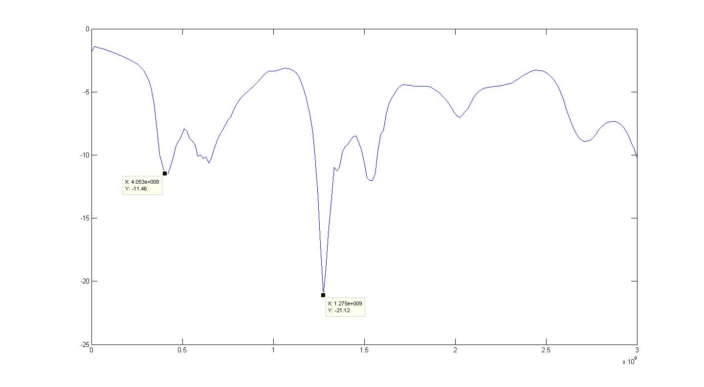
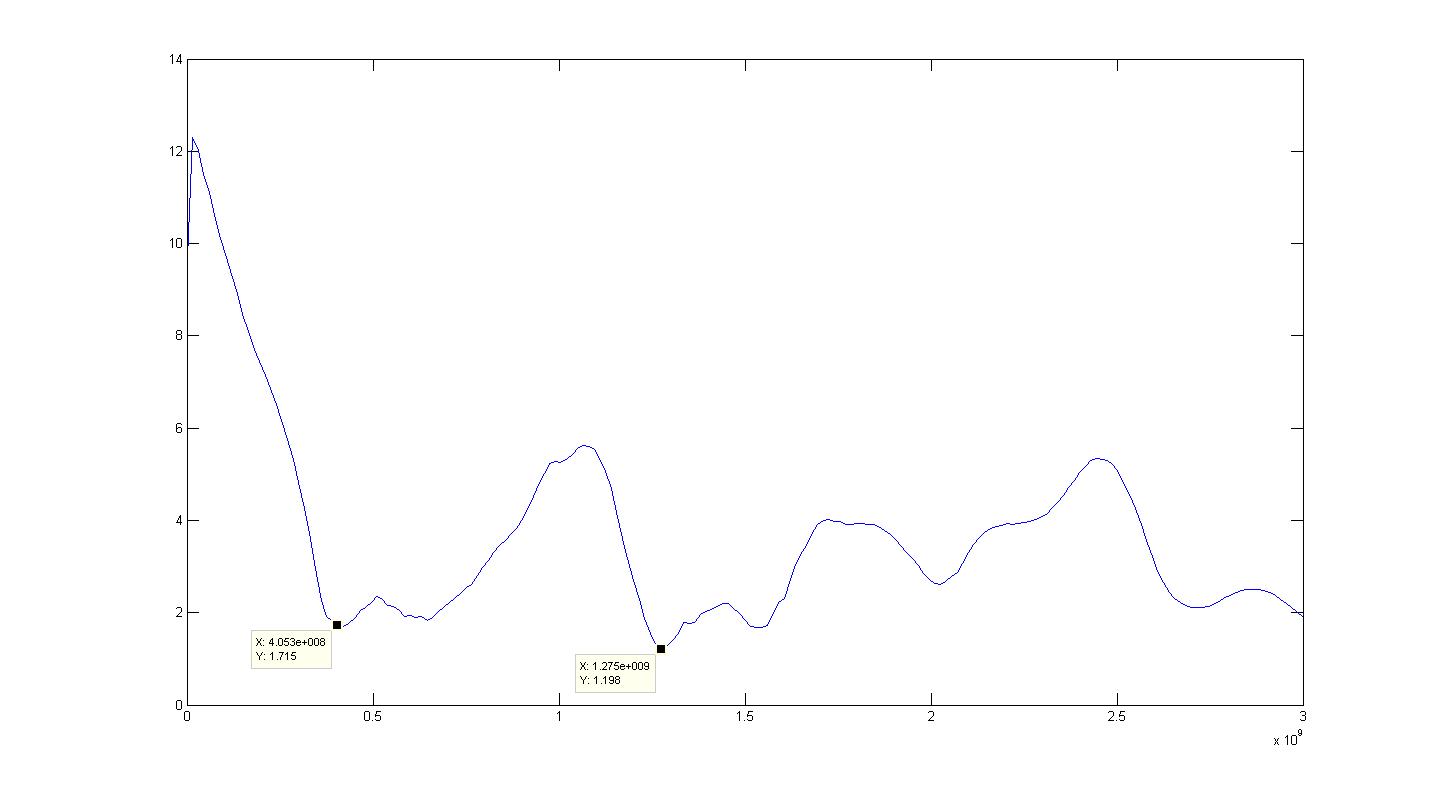
What I obtained in the VNA was this
Log
SWR
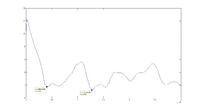
As you can see the antenna is not doing a good performance on the frequency that I want
What can be wrong?
I tried reducing the legs and the only result that I got was an almost perfect antenna for 975 MHz with legs of 8.4 cm each one.
Should I need to put a matching circuit (capacitors and inductances) after or before the balun?
In that case I should measure antenna impedance. I'm thinking to do something similar to this (page 3, top)
**broken link removed**
Anothe option is to make a lattice balun but I'm wondering how much power that balun can handle
I'm trying to avoid a balun made with coaxial cable because I'm also looking for impedance matching. The best balun for a dipole antenna could be a 1:1 that means a SWR of (at least) 1:1.5, but, if there's no other option I think that I choose it.
As a general question, How can I test the antenna to see if it is well balanced? Can I do that with a VNA, Spectrum analyzer?
Any ideas or suggestion to improve my antenna will be welcome!
Many thanks.
Reagrds
M.
I'm trying to make a dipole antenna for UHF (433 MHz). I have a 50 Ohm unbalanced output so I need to balance it and do an impedance matching to get the best performance possible. I bought some Minicircuits' ADT1.5-1 (https://www.minicircuits.com/pdfs/ADT1.5-1.pdf) to do the job.
I made a PCB, soldered the transformer and the legs of the dipole obtaining something like this.

Lengths of the legs were calculated for the frequency given (about 16.5 cm)
What I obtained in the VNA was this
Log
SWR
As you can see the antenna is not doing a good performance on the frequency that I want
What can be wrong?
I tried reducing the legs and the only result that I got was an almost perfect antenna for 975 MHz with legs of 8.4 cm each one.
Should I need to put a matching circuit (capacitors and inductances) after or before the balun?
In that case I should measure antenna impedance. I'm thinking to do something similar to this (page 3, top)
**broken link removed**
Anothe option is to make a lattice balun but I'm wondering how much power that balun can handle
I'm trying to avoid a balun made with coaxial cable because I'm also looking for impedance matching. The best balun for a dipole antenna could be a 1:1 that means a SWR of (at least) 1:1.5, but, if there's no other option I think that I choose it.
As a general question, How can I test the antenna to see if it is well balanced? Can I do that with a VNA, Spectrum analyzer?
Any ideas or suggestion to improve my antenna will be welcome!
Many thanks.
Reagrds
M.