Continue to Site

Welcome to EDAboard.com

Welcome to our site! EDAboard.com is an international Electronics Discussion Forum focused on EDA software, circuits, schematics, books, theory, papers, asic, pld, 8051, DSP, Network, RF, Analog Design, PCB, Service Manuals... and a whole lot more! To participate you need to register. Registration is free. Click here to register now.

diode IV curve simulation

Status
Not open for further replies.

coolsummer

Junior Member level 3
Joined
Mar 18, 2019
Messages
28
Helped
0
Reputation
0
Reaction score
0
Trophy points
1
Activity points
477
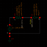
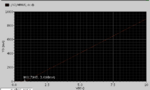
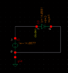
Hi,I‘m a beginner in IC......As we know, the i–v relationship of diode In the forward region is closely approximated by exponential function, but my simulation result is a linear fuunction....The X-axis is the current and the Y-axis is the supply voltage.....The simulator is spectre,the resistor and diode are from tsmc180 pdk......Can anybody tell me what's wrong with my simulation...
 

Attachments

  • 1.png
    1.png
    9.3 KB · Views: 199
  • 2.png
    2.png
    5.9 KB · Views: 178

Nothing is wrong. Just the usual IV curve of a series combination of diode and a resistor. The resistor linearizes the diode exp behavior.
 
Look at the voltage across the diode, not the supply voltage.
well I understanded. But if I move the resisror and let the Vdc directly connect to the diode,the I-V curve is still a linear function, could u tell me why it's not a exponential function in this case?
 

Attachments

  • 3.png
    3.png
    5 KB · Views: 160
  • 4.png
    4.png
    6.1 KB · Views: 155

Nothing is wrong. Just the usual IV curve of a series combination of diode and a resistor. The resistor linearizes the diode exp behavior.
well if I move the resisror and let the Vdc directly connect to the diode,the I-V curve is still a linear function,why it's not a exponential function in this case?
 

Attachments

  • 3.png
    3.png
    5 KB · Views: 119

Have you looked into the model of the diode? May be they already have a series resistor there.
 

once the diode conducts, the current is controlled by the resistor,
because the voltage drop on the diode is almost constant.

as i read you r graph, the slope is 0.09846 A/V, or 10.15 V/A, or ohms
according to the schematic simulation, the voltage across the resistor is 2.09 V
and the current is 0.209 A, so you have a 10 ohm resistor

the slope you see i the simulation is determined by the resistor, not the diode.
 

As far as I understand, you are simply plotting the wrong quantities. Vdd is not the diode voltage.
 

once the diode conducts, the current is controlled by the resistor,
because the voltage drop on the diode is almost constant.

as i read you r graph, the slope is 0.09846 A/V, or 10.15 V/A, or ohms
according to the schematic simulation, the voltage across the resistor is 2.09 V
and the current is 0.209 A, so you have a 10 ohm resistor

the slope you see i the simulation is determined by the resistor, not the diode.
But if I move the resisror and let the voltage source directly connect to the diode,the I-V curve is still a linear function, why it's not a exponential function in this case?
 

when you say you move the resistor, i take it you swapped
positions of the resistor and diode
that doesn't change the current or the voltage across the diode, and
therefore doesn't change the voltage across the resistor

as FvM says, vdd is not the diode voltage
what did you plot?
 

    coolsummer

    Points: 2
    Helpful Answer Positive Rating

    tangxm1114

    Points: 2
    Helpful Answer Positive Rating
The diode has its own "internal" resistance and
at some current this will begin to dominate
even if you add none externally.

Try lowering the Y axis max value to something
that's "sane" in the context of IC device sizes.
Like maybe 1mA max.
 

    coolsummer

    Points: 2
    Helpful Answer Positive Rating

    tangxm1114

    Points: 2
    Helpful Answer Positive Rating
when you say you move the resistor, i take it you swapped
positions of the resistor and diode
that doesn't change the current or the voltage across the diode, and
therefore doesn't change the voltage across the resistor

as FvM says, vdd is not the diode voltage
what did you plot?
sorry, I mean remove the resistor and let the Vdc directly connect to the diode,the I-V curve is still a linear function
 

Sure, above a certain voltage respectively current level, the internal diode series resistance dominates and the I/V characteristic becomes linear.

Using a voltage source is basically a bad idea. I would consider the useful current range according to diode geometry and then sweep a current source.
 
sorry, I mean remove the resistor and let the Vdc directly connect to the diode,the I-V curve is still a linear function


If you connect the voltage source directly across the diode and you sweep that voltage source you are really pushing high currents through the diode. Diode is trying to clamp its voltage to 0.7 or thereabout but you are forcing more than that and that means very big currents, which also means that any internal resistor that's modeled will certainly show up. Instead of a voltage source, use a current source.
 
Status
Not open for further replies.

Part and Inventory Search

Welcome to EDABoard.com

Sponsor

Back
Top