Continue to Site

Welcome to EDAboard.com

Welcome to our site! EDAboard.com is an international Electronics Discussion Forum focused on EDA software, circuits, schematics, books, theory, papers, asic, pld, 8051, DSP, Network, RF, Analog Design, PCB, Service Manuals... and a whole lot more! To participate you need to register. Registration is free. Click here to register now.

Diode connected NPN vs PNP

Status
Not open for further replies.

L.A.W.

Newbie level 6
Joined
Jun 28, 2011
Messages
14
Helped
1
Reputation
2
Reaction score
1
Trophy points
3
Activity points
0
Hello everyone,

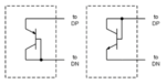
I am currently using a device that is designed to measure temperature from a diode connected BJT. The current data illustrates a 0.5 C difference between an NPN or a PNP transistor that is connected as a diode.

For the NPN case, the base-collector is shorted and a series of small currents are forced into this base-collector node (ranging from 10uA to 180u) and the \[\Delta\]Vbe is calculated. The PNP case is very similar. The base-collector is shorted together; however, current is forced through the emitter.

Attached is a photo of the connections.

There should be no difference in temperature measurements with all things being equal; i.e., same constant currents, same biasing at DP/DN (see photo), same length of PCB traces.

Is there something that I am not considering with NPN and PNP that may make a difference?
 

Attachments

  • transistor.png
    transistor.png
    28.8 KB · Views: 254

You'll also get differences between NPN or PNP types because each type has different area and bulk resistance. A transistor temperature sensor can't be expected to have 0.5 K accuracy without calibration.
 

You'll also get differences between NPN or PNP types because each type has different area and bulk resistance. A transistor temperature sensor can't be expected to have 0.5 K accuracy without calibration.

Can you elaborate a little more? The NPN and PNP in question are off the shelf 2N3904 and 2N3906. The diode equation taken at 2 or more currents to calculate a change in Vbe then re-arranged for temperature includes no additional variables for an NPN or PNP.

Devices on the market have built in features that calibrate out series resistance (pcb traces, substrate resistances, package lead resistances), beta, and ideality.


So I am faced with, 1) what am I missing from my theoretical model of a BJT? What possible 2nd or 3rd order effects would I have to consider, or 2) the test setup and thus the test data is wrong. Perhaps 3) a little of both
 

You didn't clarify if (and how) bulk resistance is compensated with your measurement.

I presume that the used transistor equations still involve some idealization. What's the specified accuracy?
 

You didn't clarify if (and how) bulk resistance is compensated with your measurement.

I presume that the used transistor equations still involve some idealization. What's the specified accuracy?

Yes, the equation being used is the ideal diode equation:
T (in Kelvin), q, k, n, Is, and Iforced.

Using 3 or more forced currents allows series resistance to drop out after a delta Vbe is measured and some algebra re-arranging.

The accuracy is 0.5C at when operated from -40 to 125C.

The data supports an NPN transistor, but not a PNP. The claim so far is that a PNP is not compatible and I do not agree. As far as my knowledge, there is *no difference* in an NPN or PNP. It is simply a matter of biasing for transistor action. Perhaps doping? NPNs majority carries are electrons while PNPs are holes? Even if that were true, how can that be modeled?

Now, this application uses BJTs as diodes as shown in my first screencap. So what, if any, difference would there be that I may not be considering that is causing a temperature error in my measurement?

I say there should be no difference and the measured differences are from practical mistakes: bad soldering, flux, poor connection, etc.
 

Hi L.A.W.,

Take into account that you source your input current I_in into base (and collector) for NPN case and into emitter for PNP case. Thus:

1) NPN: I_in = Ic + Ib
2) PNP: I_in = Ie

this is a difference. Maybe it is a difference that you're looking for.


Try to sink I_in from emiter and base of PNP to have the same test circuit as in NPN case and then compare.
 

Yes, the equation being used is the ideal diode equation:
T (in Kelvin), q, k, n, Is, and Iforced.

The data supports an NPN transistor, but not a PNP. The claim so far is that a PNP is not compatible and I do not agree.
We can hardly discuss the said models and equations without seeing it.

The equations I'm familiar with (e.g. SPICE model equations) have a certain range for involved constants, so they can give slightly different results for NPN and PNP.

- - - Updated - - -

1) NPN: I_in = Ic + Ib
2) PNP: I_in = Ie

You forgot line 3
Ie = Ic + Ib (by application of Kirchhoff's first law) https://en.wikipedia.org/wiki/Kirchhoff's_circuit_laws
 

What I meant and what I wanted to show as simply as possible using math equations is the fact that the input current in NPN case creates base and collector currents that are summed up to emitter current. In PNP case input current creates emitter current that is then split into base and collector currents. That's a difference. That's why PNP case should be constructed such that input current should be sinked not sourced. Thus, PNP case will be identical as NPN case. Then we can compare.

Of course Ie = Ib + Ic, but this is not what I wanted to underline. Here are more detailed equations ;) :

1) NPN case: I_in = Ic + Ib = Ie
2) PNP case: I_in = Ie = Ic + Ib

and yes, in that case order from left side to right side matters.
 

in that case order from left side to right side matters.
Are you trying reinvent electrical circuit theory?

The order does not matter. Both transistors are forward biased at Vbe = Vce, that's all.
 

Through math (and I see it was a bad idea) I wanted to show my point that test circuits differ. It is a small difference, but maybe in this case where 0.5 C difference is being searched for this is the case? I do not know.

In order to have the same test circuits, input current I_in should be sinked from base and collector in PNP case.

I do not claim, that this will be the solution for the problem. I just wanted to point that test circuits differ. However, the author is aware of this.
 
Last edited:

We can hardly discuss the said models and equations without seeing it.

The equations I'm familiar with (e.g. SPICE model equations) have a certain range for involved constants, so they can give slightly different results for NPN and PNP.

- - - Updated - - -

It's the standard diode equation. Using 2 currents through a PN junction to generate a delta-Vbe. "Remote Diodes Yield Accurate Temperature Measurements" may be referred to the equations; jump to equation 4 for the delta-Vbe on pg. 2.

https://www.edn.com/design/test-and...iodes-yield-accurate-temperature-measurements

I contend that using equation 4 for an NPN or PNP will not yield different results in temperature, and it will not. Something is missing in the model between NPN or PNP or it is a practical measurement issue.

You forgot line 3
Ie = Ic + Ib (by application of Kirchhoff's first law) https://en.wikipedia.org/wiki/Kirchhoff's_circuit_laws

What I meant to say is that the forced current for the NPN case will be equal to Ic+Ib since they are shorted together. For the case of the PNP circuit, the force current is through the emitter.
 

I see several empirical parameters discussed in the paper that are assumed to have a certain value, e.g. the said "nonindeality factor". In so far it's more a guess than certainty that different batches of 2N3904 and 2N3906 always show exactly the same characteristic. The usual transistor sensor application in CPU chip temperature measurements would have no problems with 0.5 (or slightly higher) temperature offsets.
 

I see several empirical parameters discussed in the paper that are assumed to have a certain value, e.g. the said "nonindeality factor". In so far it's more a guess than certainty that different batches of 2N3904 and 2N3906 always show exactly the same characteristic. The usual transistor sensor application in CPU chip temperature measurements would have no problems with 0.5 (or slightly higher) temperature offsets.

Yes, that is true; however, I presume by the lack of a definitive answer that there really is no difference between NPN and PNP at least to first order.

I can account for series resistance, beta, and ideality.

So it really does sound like a practical measurement problem with equipment or setup.
 

You insist to use the "standard diode equation" but I'd bet you
have nothing for n or Is, which are the primary fitting params.

PNP devices often have inferior collector resistance and since
you want to operate at Vbe(ext)=Vce(ext) you may be running
into onset of saturation at higher temp and higher currents,
with this bending the hFE-vs-Ic curve (which, hFE, is what
linearizes the transdiode relative to what you'd get from the
E-B junction alone - more decades of log-linearity, suppressing
the series resistance).

Switching transistors may employ charge gettering features
in the base and collector which make saturation worse in the
sense of Vce(sat) achievable (and there lies your margin
against Vbe-Ic*Rc, Vbe=Vce(ext)). Shorted-junction plugs
and the like take you away from idealized models at higher
level injection.

It would not be the least bit surprising to see base doping differ
by factors of 2-5 between NPN and PNP, especially when you
are talking about devices that aren't even asserted to be
"complementary" and are not co-processed. Complementary
vertical bipolar technologies at least used to take a stab at
gross matching of Vbe(NPN):Vbe(PNP) but in discrete world,
you'd have to dig.
 

You insist to use the "standard diode equation" but I'd bet you
have nothing for n or Is, which are the primary fitting params.

I have been away from this project, but jumping back onto it. I am not sure about your concern. When solving the diode equation for Vbe and then using two currents to generate 2 Vbes, the delta-Vbe reduces the saturation current variable to 1. The ideality remains, but that is known. Or at least known by characterization done for many different NPNs from manufacturing.

We presumed the same ideality for PNP. Is this not the case? If not, perhaps this is the error in question causing heartburn.

PNP devices often have inferior collector resistance and since
you want to operate at Vbe(ext)=Vce(ext) you may be running
into onset of saturation at higher temp and higher currents,
with this bending the hFE-vs-Ic curve (which, hFE, is what
linearizes the transdiode relative to what you'd get from the
E-B junction alone - more decades of log-linearity, suppressing
the series resistance).

Switching transistors may employ charge gettering features
in the base and collector which make saturation worse in the
sense of Vce(sat) achievable (and there lies your margin
against Vbe-Ic*Rc, Vbe=Vce(ext)). Shorted-junction plugs
and the like take you away from idealized models at higher
level injection.

It would not be the least bit surprising to see base doping differ
by factors of 2-5 between NPN and PNP, especially when you
are talking about devices that aren't even asserted to be
"complementary" and are not co-processed. Complementary
vertical bipolar technologies at least used to take a stab at
gross matching of Vbe(NPN):Vbe(PNP) but in discrete world,
you'd have to dig.

I did run my own sim in TINA spice using an NPN and a PNP. I do see a difference in delta-Vbe, so this may be something of interest to look into. The currents in the lab being used are very low; <100uA. I don't think saturation of Vce is the issue, but I'll certainly look at it again.
 

I did run my own sim in TINA spice using an NPN and a PNP. I do see a difference in delta-Vbe, so this may be something of interest to look into. The currents in the lab being used are very low; <100uA. I don't think saturation of Vce is the issue, but I'll certainly look at it again.
The unsaid prerequisite is that the used transistor model parameters exactly reproduce the nonideal device behaviour, including the small differences between NPN and PNP. Possible but not neccessary.
 

Status
Not open for further replies.

Similar threads

Part and Inventory Search

Welcome to EDABoard.com

Sponsor

Back
Top