takbbb
Junior Member level 2
i am making a dimmer circuit
and i find a source on it in microchip
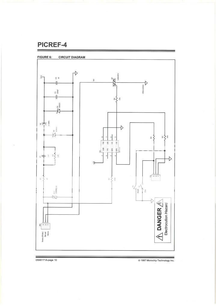
https://ww1.microchip.com/downloads/en/AppNotes/40171a.pdf
however the circuit have a R2 (1M ohm) in series with the power line
i wonder then how many current can be drive ???
as i connected the same circuit(with other atmel MCU) , the 1M have limited the current .....
so how does it work ??( i assume the Vcc = 5V in the circuit)
sorry the pic is uprighted..
and i search on the web which other circuit also have such 1M resistor
and i find a source on it in microchip
https://ww1.microchip.com/downloads/en/AppNotes/40171a.pdf
however the circuit have a R2 (1M ohm) in series with the power line
i wonder then how many current can be drive ???
as i connected the same circuit(with other atmel MCU) , the 1M have limited the current .....
so how does it work ??( i assume the Vcc = 5V in the circuit)
sorry the pic is uprighted..
and i search on the web which other circuit also have such 1M resistor