Continue to Site

Welcome to EDAboard.com

Welcome to our site! EDAboard.com is an international Electronics Discussion Forum focused on EDA software, circuits, schematics, books, theory, papers, asic, pld, 8051, DSP, Network, RF, Analog Design, PCB, Service Manuals... and a whole lot more! To participate you need to register. Registration is free. Click here to register now.

Digital thermometer problem

Status
Not open for further replies.

mohsen 2012

Member level 4
Joined
Jul 3, 2012
Messages
70
Helped
0
Reputation
0
Reaction score
0
Trophy points
1,286
Activity points
1,796
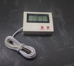
Hello , please can anyone tell me what is the temperature sensor used in this digital thermometer , it have 2 pins ::


12595942_915871345164128_1241236969_n.jpg

12648089_915871205164142_1632160277_n.jpg
 

I can't see anything I can definitely identify as a temperature sensor. If there's something at the end of the wire, it's too small and too fuzzy to see clearly even in full size, at least for me. If you can post a clear close-up image, perhaps some of us will be able to tell you.
 

First look at the commercial thermometer :
Freezer-thermometer-HT-5-electronic-LCD-digital-temperature-display-External-Sensor-Integration-.jpg
I buy this thermometer for use it into my home-made etch tank and i wrap the metal sensor with Adhesive tape
but the ferric chloride has Spent the sensor !!!
I did not find the datasheet of the thermometer , so i want to know wich sensor maybe used in this thermometer , i know the LM35 but it have 3 pins .
 

Some 1-wire sensors use only two wires (if that makes sense!) in parasitic power mode but almost certainly that unit uses a thermistor.

Try wiring a variable resistor (suggest ~50K) across the two wires and see if adjusting it makes the reading change. If it does, the next step is to work out what thermistor can be used as a replacement. It will probably be impossible to find the exact part but you can probably get one that is accurate enough. You need to find the resistance that gives the correct reading at two temperatures. Turn the variable resistor to give a reading of 0C (freezing point of water) and using a testmeter, measure the resistance. Then adjust it to say 25C and measure it again. You can compare the two resistances with the graphs on thermistor data sheets to find a close match.

Brian.
 

Yes....adjusting the potentiometer it makes the reading change i use a 50k pot
 

Farnell have over 1,200 types in stock!

Moshen2012, what you need to do is find the resistances that give particular readings, ones near to each end of the expected range are probably best. Note the reading and the resistance, then use the graphs in thermistor data sheets to find one that matches your values.

Hint: there are two basic types of thermistor, PTC and NTC. A PTC will increase in resistance as the temperature goes up, and an NTC will drop in resistance as the temperature goes up. Discover which you need, it will make selection much easier.

Brian.
 

Yes....adjusting the potentiometer it makes the reading change i use a 50k pot
Fine. Determining a few points with exact kohm and temperature values can help you to narrow down the sensor type (NTC, PTC, diode) and possibly find a replacement.
 

Status
Not open for further replies.

Part and Inventory Search

Welcome to EDABoard.com

Sponsor

Back
Top