gres
Full Member level 4
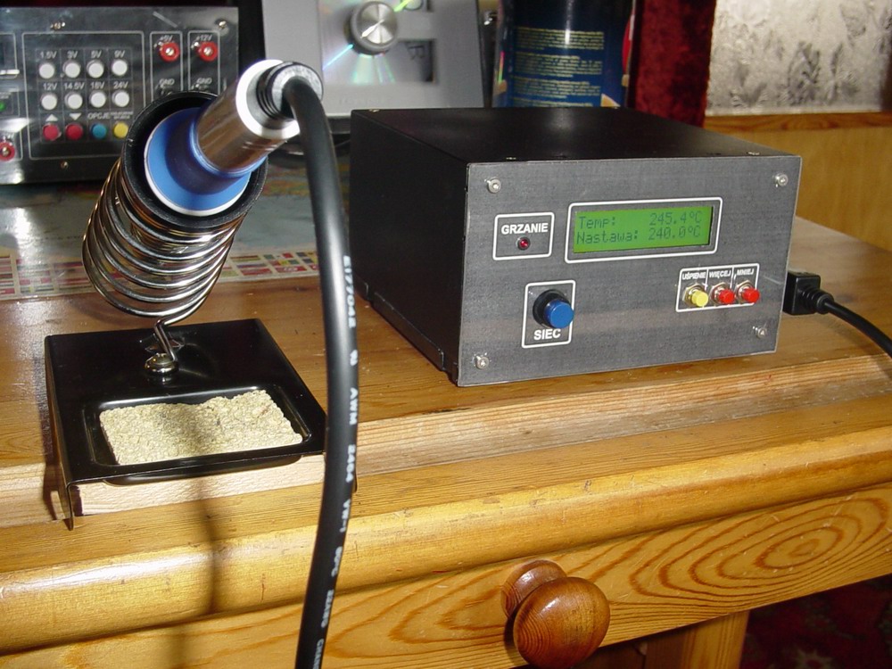
Soldering iron station consist the same hand as in model SL 10/20/30. Head of soldering is good quality, all construction is light.
Software for station I made in BASCOM, to measure voltage controller use 10 bit A/C converter. Voltage that goes to A/C converter is provisionally reinforcement x 100 by operating amplifier, thanks to that we have maximum resolution of converter - with 22mV at outout of thermosteam 2,2V at output of amplifier. As a temperature conversion rate from thermosteam output i used voltage factor measured by A/C converter, althought it's not the best way to check temperature of head but for our need is enought. Better could be temperature compensation of cold ending of thermosteam and PWM signal, but as i said it's just a solder and we don't need 50C accuracy.
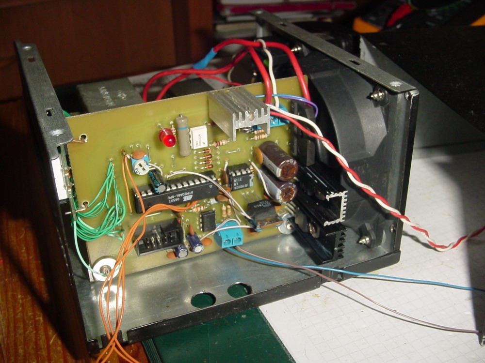
Control system is based on diagram from EP article about soldering iron station,
Tool consist detector - phase ground, thanks to that when head temperature fall to set level, triac that is responsible for turning on/off the heater, will be set at moment when phase goes through zero, thanks to that there's no way to sudden current increase.
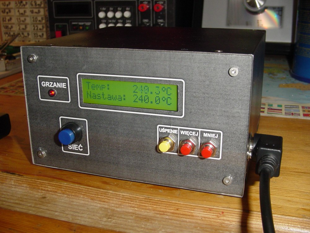
To set temperature we have two buttons - up and down, and sleep button. After switch to sleep mode, system goes to 1300. Next press is normal work mode and temperature goes to previously. Station could be turn off at any time. After turn on setup is the same as before turn off. At display we can see current temperature and set temperature. At sleep mode display is current temperature. When the heater is on , at front panel we have red LED.
Board is made by thermotransfer mode, display has 2x16 marks. There is also 12V cooler, that is connect to 5V ( slower and more quite).
Panel is designed in Corel and covered by perxpex. As a casing I used computer power supply.
More information and diagrams are here https://www.elektroda.pl/rtvforum/topic1426196.html