Continue to Site

Welcome to EDAboard.com

Welcome to our site! EDAboard.com is an international Electronics Discussion Forum focused on EDA software, circuits, schematics, books, theory, papers, asic, pld, 8051, DSP, Network, RF, Analog Design, PCB, Service Manuals... and a whole lot more! To participate you need to register. Registration is free. Click here to register now.

Digital Meter Wiring Help

Status
Not open for further replies.

Diesel88

Newbie level 4
Joined
Dec 9, 2013
Messages
6
Helped
0
Reputation
0
Reaction score
0
Trophy points
1
Activity points
50
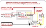
I have a digital Volt / Amp meter rated: Operating voltage: DC 4.5 ~ 30V, Measure voltage: DC 0 ~ 100V, Measure current: 100A (require external shunt), Operating current: <20mA.

This meter has a Black / Red wires for the 4.5 – 30VDC power to the meter and 3 wires Red / Black / Yellow to connect to the load. The meter came with a shunt but it says if my measured amps are 10 or less, the shunt is not required

I want to measure the output volts / amps of a power supply unit, 120VAC input, and 36VDC / 9.7A output.

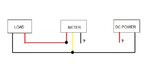
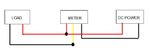
No problem to connect the power to the meter, I see the volts but I see 0 Amps because I don’t know how / where to connect the 3 wires

Any help would be appreciated

Thanks
 

At a guess the black wire is the common earth, the red is for voltage input and the yellow for current. To check this measure the resistance between the yellow and black wires, it should be very low, less then one ohm. If it seems to be like this. Try, red to PSU + output, black to PSU - output, yellow to load -.
Frank
 

Thank you Frank for the help

Measuring between the yellow / black looks like there is no continuity because my tester shows just 1. Perhaps I should have the power to the ampmeter connected?

When you say "Try, red to PSU + output, black to PSU - output, yellow to load" the yellow to load where is connected? I mean the load has red / black wires so where do I connect the yellow?


Anyway the attached schematic works for me but I wanted to try without the shunt since the schematic says for anything less than 10A, the shunt is not required.

If I don’t connect the shunt, how the wiring will be connected?
 

Attachments

  • Ampmeter.JPG
    Ampmeter.JPG
    56.9 KB · Views: 77

Sorry Frank but I don't see where the black from the DVM and the red from the power supply will go

Perhaps on the attached simple schematic you can tell me how?

Thank you
 

Attachments

  • Meter Schematic.JPG
    Meter Schematic.JPG
    18.3 KB · Views: 80

1. Join all the red wires together, this is so the volt meter can measure the power supply lead to the load and provide positive volts to the load.
2. Join the power supply black lead to the black lead of the DVM, this provides the negative for the voltmeter and allows current to flow into the DVM.
3. Join the yellow wire from the DVM to the black lead of the load, this is so current can flow out of the DVM into the load.

Frank
 
Now at least in paper I understand the connections. I will try tonight to get it working

Thanks so much Frank
 

It worked Frank but……….

My experiment with this Volt / Ampmeter is with a 12VDC /5A power supply unit along with a 12VDC computer cooling fan. I hope I understood correctly but when I connect everything as per attached schematic the amps reading took a few seconds to show a value of 99.9A; then I unplugged everything to prevent possible damage

The same set up but with the wiring connected to include the shunt showed a reading of 0.7A which is more likely for a small fan

I'm just curious now to see how the connections can be made without a shunt but I wonder if it's a good idea to use the shunt despite that the vendor said "for less than 10A current the shunt is not required"
 

Attachments

  • W. Schematic.JPG
    W. Schematic.JPG
    17.6 KB · Views: 76

I understand your point Frank, you get what you pay for LOL. I only paid $14 shipping included from China so I dont expect a top of the line meter

There is at the back two adjusting screws for the volts and amps calibration. If I connect the DVM as per my last schematic and it will show 99.9A do I have time to play with the amp calibration screw or it will burn something?

I also use 22 gauge wiring for this experiment, does it matter? For the final connections I plan to use 16 or 18 AWG
 

Status
Not open for further replies.

Part and Inventory Search

Welcome to EDABoard.com

Sponsor

Back
Top