Continue to Site

Welcome to EDAboard.com

Welcome to our site! EDAboard.com is an international Electronics Discussion Forum focused on EDA software, circuits, schematics, books, theory, papers, asic, pld, 8051, DSP, Network, RF, Analog Design, PCB, Service Manuals... and a whole lot more! To participate you need to register. Registration is free. Click here to register now.

Digital electronics circuit design

Status
Not open for further replies.

maulik_suthar

Junior Member level 1
Joined
Aug 28, 2011
Messages
19
Helped
0
Reputation
0
Reaction score
0
Trophy points
1,281
Activity points
1,472
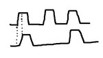
i want the circuit and a proper method to Design a black box whose input clock and output relationship as shown in diagram.
__ __ __ __ __ __ __ __ __
__| |__| |__| |__| |__| |__| |__| |__| |__| |__ <<<<<<< clock
__ __ __ __ __
__| |_ _____| |______| |______ | |______| |__ <<<<<<< Output
 

actually i thought of that but the problem is that the op of the divide by 2 circuit will be high for whole cycle till next posedge of clock, but here it goes low whenever a negedge of same cycle, so i need a more optimized circuit rather than just divide by 2
 

Can you use microcontroller to generate the output for your clock or do you have to use only digital logic circuit? What I am saying is you can count the frequency of your input clock and generate the output frequency as needed. See image. You will get something like that. Will your clock be synchronized with some other circuit also?
 

Attachments

  • clk.jpg
    clk.jpg
    11.7 KB · Views: 56
Last edited:

Status
Not open for further replies.

Similar threads

Part and Inventory Search

Welcome to EDABoard.com

Sponsor

Back
Top