Continue to Site

Welcome to EDAboard.com

Welcome to our site! EDAboard.com is an international Electronics Discussion Forum focused on EDA software, circuits, schematics, books, theory, papers, asic, pld, 8051, DSP, Network, RF, Analog Design, PCB, Service Manuals... and a whole lot more! To participate you need to register. Registration is free. Click here to register now.

DIgital counter ....switching Contactor.......noise ?

Status
Not open for further replies.

jit_singh_tara

Full Member level 6
Full Member level 6
Joined
Dec 22, 2006
Messages
325
Helped
9
Reputation
18
Reaction score
4
Trophy points
1,298
Location
Delhi , India
Visit site
Activity points
4,295
Dear Friends ,

I would like to know what is the best way to drive the contactors for switching on/off motors using mcu , optocoupler etc.
Recently i tried to drive 2 contactors using 2 relays driven by the mcu.The description of ckt is as follows :

2 windings from transformer : a.)0-9 & b.)0 -14.

a.) Driving the 7805 regulator for running mcu and displays(seven segment) .
b.) Driving the coils of 2 relays 12vdc (diode in reverse added to the relays).


using pc817 to drive the transistor which turns on the relay 12vdc ,i.e mcu is turning on the optocoupler which in turn is driving the relay.The dc relay in turn is driving the contactor (running on 230 Vac)., Applied rc snubber across the contactor terminals of the contact.


Using the proximity switch (power from the input side of 5v regulator and ground of winding a.).Proximity switch is connected to hardware interrupt of the mcu (pic16f886).

The problem is 1 in 10 times the moment the contactor is turned on the counts of the proximity signal increases by say 2 to 6 or sometimes more.

So far i am able to judge that the moment the contactor is turned on there is spike on 5v output line driving the mcu.
Please suggest what to do to remove this spike from entering the unit from ac mains........
Why i am saying that the noise is entering from the ac mains is because the dc relays driving the contactor are driven by winding b.) and that too after being driven by optocoupler .

Please suggest what to do.....

I have seen a good digital counter using cd4093 in the circuit , it has schmitt trigger inputs , can someone suggest will it be useful and how.......


View attachment images.pdf
 

Remove the contactor from the relay and just switch on off the output lines, so that you can confirm the problem is coming from contactors.

If you confirm it was the contactor then put some 0.1uF capacitors in the power supply near all ICs and also check the proximity sensor output for noise, If you see some better use some delay circuits or build some delay mechanism in software between the interrupt detection..
 

If i run only the contactors without motor connected, problem is very less , if the motor is connected then there is problem .

I cant run the motor directly on relays as the relays are rated 5A@250 Volts , moreover the system is using contactors only , cant replace them , they have to be used .

Need to sense rotations of a motor and then reverse the direction after acertain counts .But as i told moment the contactor switches on the motor there is jump in the pulses read by proximity.... which i believe is due to the spike generated on contactor switching on the motor ..
 

I mean to remove the contactor completely from the circuit and just give rotate the wheel by your own and make sure that the noise is coming from the contactor..
 

Hi,

show us your schematic and your layout, so we can better understand your circuit.

Klaus
 

Impulse currents cause both conducted and radiated noise.

For conducted noise filter the source and signal response with suitable choke and capacitor for noise source and RC filter for signal being sensed Schmitt trigger logic improves immunity for counting.

For radiated noise , reduce area of loop current both for noise source with twisted pair and or shielded wire then position wires with right angles to sensor wire and noise current.
 

Dear Friends ,

please find the attached files....:

1. power supply card .
2. Microcontroller card .
3. Display card .
 

Attachments

  • 1792.pdf
    38.2 KB · Views: 69
  • 1793.pdf
    66 KB · Views: 59
  • 1794.pdf
    37.3 KB · Views: 63
  • SCH_1792.pdf
    21.2 KB · Views: 83
  • SCH_1793.pdf
    26.2 KB · Views: 69
  • SCH_1794.pdf
    19.4 KB · Views: 70

Lets start from power supply
SCH_1792.pdf Is the same power circuit you are using in your project?

Why do you need that pin 8 of T1 transformer to bridge ?
What are all the turns or voltage ration of the transformer..
 

hi,


6,7,8 is of the centre tapped winding going to upper bridge (D1,D2,D3,D4).

9,10 is another winding for lower bridge(D5,D6,D7,D8)

Dont go by the wiring in case of transformer , it is wrongly shown in the schematic but in actual it is as mentioned above....

- - - Updated - - -

Upper bridge is producing the Vcc , -5V and +9 V .

Lower bridge is producing +14V unregulated as you can see . this is the supply which is going to the relays .
 

If you really make the same connection as your schematic in power circuit, you will end up with unwanted current flow in the transformer like a short circuit also chances for getting diode damaged..

Other than that If you sure the noise is coming from the contactor, then try decoupling capacitors and shielding the sensor wires also schematic triggers is the best option.
 

The circuit is running fine , Transformer is also not heating , and diodes are also fine , the transformer o/p and diodes are correctly connected .....


In the schematic ,
8,9,10 is shown as centre tapped winding and 6,7 is shown as other 12 volt winding. which is not right( sorry for that winding diagram).

In actual in the pcb of 1792 , you can see that :

6,7,8 is of the centre tapped winding going to upper bridge (D1,D2,D3,D4).
9,10 is another winding for lower bridge(D5,D6,D7,D8).
 

As I said already If you are plenty sure about contactor put decoupling caps, try shielding and schmitt trigger circuit. thats all the way..

What counter or controller you are using ? can you post the code ?
If you are using controller try some reliable ones or we can do whatever want with code..
 

I restrict my comment to two points.

Presumed the unwanted event counting at interrupt input is the only problem you observe presently, you should try with a filter capacitor soldered directly between INT and VSS pin (e.g. 1 - 10 nF, depending on the pulse speed in regular operation). Secondly a series resistor between J3 and INT input, e.g. 1 k.

Apart from this problem, I want to mention that the mains voltage isolation on the power supply board is insufficient for a 230 V circuit. In the lowest overvoltage category, 1.6 mm spacing is absolutely required., usually applied standards demand 3.3 or even 6 mm for safe isolation of 230 VAC to exposed low voltage circuit.
 
Dear Fvm ,

thx for the help , i will make the changes as mentioned by you in the first suggestion . i.e adding filter cap 10nf and adding resistor 1k in between j3 and filter cap....
I will tell you the result of that soon .

PLease elaborate the second point ...." I want to mention that the mains voltage isolation on the power supply board is insufficient for a 230 V circuit. In the lowest overvoltage category, 1.6 mm spacing is absolutely required., usually applied standards demand 3.3 or even 6 mm for safe isolation of 230 VAC to exposed low voltage circuit.
".

I didnt understand that .... please mention with respect to the pcbs.......attached......
 

I don't believe that my statement is so hard to understand...

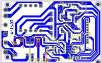
In the below picture, the red lines mark violations of required separation for safe isolation. The yellow lines mark possible conflicts with distance rules inside the 230V net class.

The lower and upper left screw holes may also involve distance rule violations.

 
Status
Not open for further replies.

Similar threads

Part and Inventory Search

Welcome to EDABoard.com

Sponsor

Back
Top