Continue to Site

Welcome to EDAboard.com

Welcome to our site! EDAboard.com is an international Electronics Discussion Forum focused on EDA software, circuits, schematics, books, theory, papers, asic, pld, 8051, DSP, Network, RF, Analog Design, PCB, Service Manuals... and a whole lot more! To participate you need to register. Registration is free. Click here to register now.

Digital contol of single supply AC Induction motors

Status
Not open for further replies.

vsmGuy

Advanced Member level 2
Joined
Jun 26, 2006
Messages
503
Helped
44
Reputation
88
Reaction score
15
Trophy points
1,298
Location
VddVss
Activity points
3,882
I want to control my overhead AC Induction Fans remotely.

That means I have to control the speed of the fans electronically.

As far as I have understood, the fans we have in our houses are Permanent split-capacitor motors.

The speed of these fans can be controlled using a TRIAC using a tuning circuit to change the firing angle.

We can also control the speed by changing the frequency of the input voltage to the fans.

What method would you recommend ? Specifically I am looking forward to a working implementatiion.

If possible, I would like to remove the capacitor (which produces an extra phase from the single phase input supply) and wire the three terminals of my fans directly to my interfacing circuit.

I am willing to use ATMEL 8051 or PIC Microcontrollers for the interfacing - I just need to know how to achieve speed control of these fans.
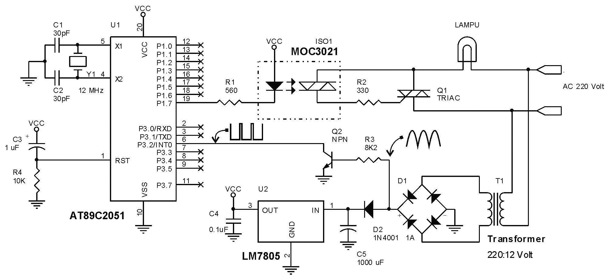
 

The speed of these fans can be controlled using a TRIAC using a tuning circuit to change the firing angle.
This method named AC phase control, can be implemented with 8051 like this:
6_1175229618.gif

Code:
   ORG $0
   LJMP Start          ; Main program
   ORG $3
   LJMP ZeroCrossing   ; Zero crossing detector
   ORG $B
   LJMP TriggerTRIAC   ; Trigger TRIAC
;
Start:
   MOV  TMOD,#1        ; Timer0 mode
   SETB EX0            ; enable INT0 interrupt
   SETB IT0            ;  ‘1’ ke ‘0’ transition
   SETB EA             ; enable system interrupt
   MOV  B,#5           ; P/Pmax = 0,5
   SJMP *              ; program utama
;
ZeroCrossing:
   MOV  DPTR,#DelayTime
   MOV  A,B            ; P/Pmax value
   MOVC A,@A+DPTR      ; get delay constant
   MOV  TL0,A          ; save to Timer0
   MOV  A,B            ; P/Pmax value
   INC  A              ; 2nd byte
   MOVC A,@A+DPTR      ; get delay constant
   MOV  TH0,A          ; save to Timer0
   SETB TR0            ; start Timer0
   SETB ET0            ; enable Timer0 interrupt
   RETI
;
*** Delay constant table
DelayTime:
   DW $FFFF-10000,$FFFF-7440,$FFFF-6550
   DW $FFFF-5940,$FFFF-5400,$FFFF-5000
   DW $FFFF-4550,$FFFF-4050,$FFFF-3380
   DW $FFFF-2710 
;
TriggerTRIAC:
   CLR  TR0            ; stop Timer0 
   CLR  ET0            ; stop Timer0 interrupt
   CLR P1.7            ; turn on MOC3021 LED 
   NOP                 ; wait a moment
   SETB P1.7           ; turn off LED MOC3021 LED 
   RETI

Change the register B value to control the power
 

    vsmGuy

    Points: 2
    Helpful Answer Positive Rating
@budhy : The circuit seems ok.. have you tested it ?

Can you explain the code to me.. just a running commentary will do...
 

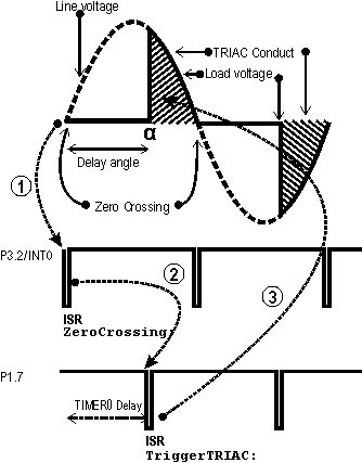
It is a fully interrupt driven code.

Every zero crossing of line voltage, µC is interrupted thru P3.2/INT0, this event is handled with ZeroCrossing: Interrupt Service Routine (ISR) as follow :
:arrow:get the delay constant from DelayTime:, this value is a time constant to control Timer0 and store at TH0 and TL0
:arrow:after that start the Timer0 and set Timer0 Interrupt

Timer0 Overflow Interrupt (TriggerTRIAC: ISR) handling :
:arrow: Clear Timer0 Interrupt
:arrow: Trigger the TRIAC thru P1.7

Illustration of the whole process
86_1175425234.gif
 

    vsmGuy

    Points: 2
    Helpful Answer Positive Rating
No no... I did not mean for you to translate the ASM code to english.... I can read ASM perfectly well :)

I am interested in knowing things like :

1. Where/how did you get the delay values ?
2. Why not calculate the pulse width of zero crossings and calculate time delay accordingly using percentage ?

These answers I am interested in :)
 

1. Where/how did you get the delay values ?
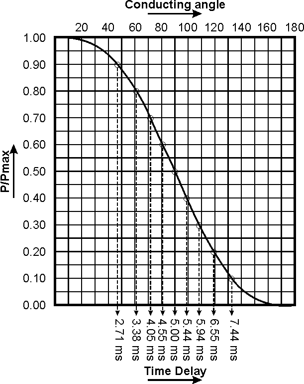
I derivate the delay value from this graph

86_1175489946.gif


2. Why not calculate the pulse width of zero crossings and calculate time delay accordingly using percentage ?
Because the P/Pmax vs time delay variation isn't linear
 

    vsmGuy

    Points: 2
    Helpful Answer Positive Rating
@budhy : I will read your posts thoroughly and get back to you :)

Can we talk via email ?
 

Hi VSM GUY
i too interested in this topic can i join with u . Cos i m currently working to control the Speed control of the fan. But i dont have any idea about the Triac circuit . i know the opeartion of the triac family . hope u both have communication with me too about this.

prabaece@gmail.com is my id
 

@budhy

Di you get my latest messages ?

BTW - I had a look the the MOC3021 datasheet and I see it requires atleast 15mA to turn on.

I think the 2051 supplies only a good 5ma... don't you think it's better to use a transistor to boost the current ?

Added after 5 minutes:

I see you are sinking in current onto the 2051 pin from the LED.. how much current can the 2051 sink.. where is it in the datasheet ?

Added after 14 minutes:

Read the 2051 DS more..

The 2051 can actually drive 20mA through port1.

So why not source current from the port ?
 

I derivate the delay value from this graph

86_1175489946.gif


Because the P/Pmax vs time delay variation isn't linear

mas budhy, i have phase firing angle circuit that would give 110vac if i applied 5ms delay. but from the graph, i will get 155vac. which one is true? is it suppose to be half power or half voltage?
 

nice work budhy

please can you help me to control the power to the load and change the relation to linear ? i need to changing the load power linearly as say 20 step

Many thanks

MedTronic
 

Status
Not open for further replies.

Part and Inventory Search

Welcome to EDABoard.com

Sponsor

Back
Top