Continue to Site

Welcome to EDAboard.com

Welcome to our site! EDAboard.com is an international Electronics Discussion Forum focused on EDA software, circuits, schematics, books, theory, papers, asic, pld, 8051, DSP, Network, RF, Analog Design, PCB, Service Manuals... and a whole lot more! To participate you need to register. Registration is free. Click here to register now.

Digital/Analog noise problem

Status
Not open for further replies.
Thanks for taking the time to check out the thread FvM.

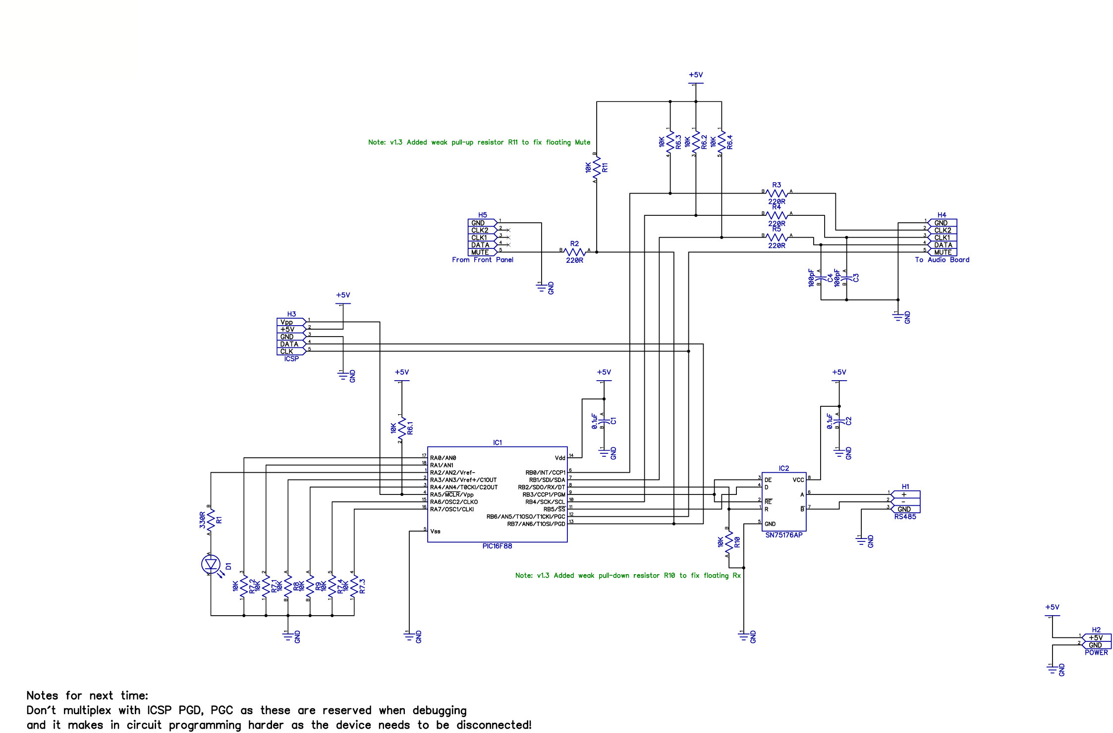
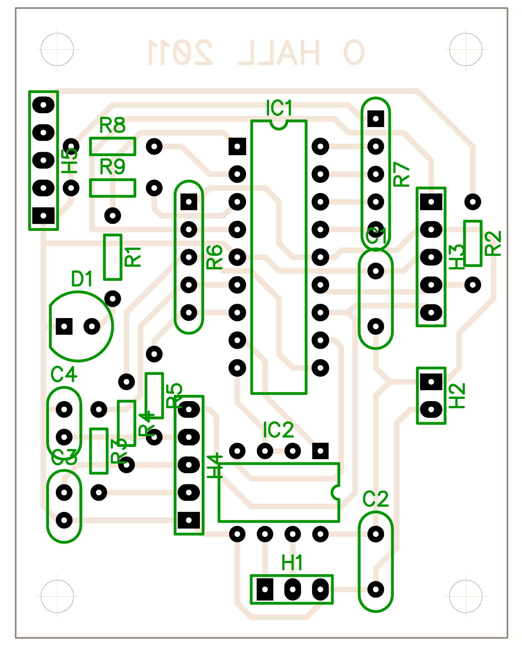
I've attached a schematic and a PCB layout for info - I don't have any photos handy, and this only relates to my side of things - I don't have schematics for the amp.


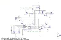
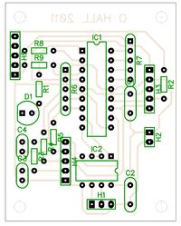
Hope you can shed some light on things!

Added: You'll see R10 and R11 don't appear on the PCB - I had to bodge these directly onto the board - Once I can fix the noise issue I'll do a new PCB design.
 

The add-on board design is clear so far. One could discuss, if adding stronger ground traces and a meshed ground (using jumpers) would be reasonable. But don't expect, that it has much impact on the crosstalk problem.

In addition it would be interesting, at which locations the cicruit is wired to the amplifier, if you e.g. have multiple ground connections.

You can also do some tests to narrow down the problem:
- clarify, that the crosstalk is actually generated by the RS485 communication, not the data signals that go to the board. I'm sure, you'll find a setup to distinguish both.
- operate the digital board with an isolated supply for test, the only ground connection to the amplifier would be along with the data interface.
 

Thanks FvM,

Answers below:

In addition it would be interesting, at which locations the cicruit is wired to the amplifier, if you e.g. have multiple ground connections.

I do have three - possibly four - grounds to the amp. The power supply ground has been tied to the amp's power supply ground just after the bridge rectifier and caps, but there are also grounds from connectors H4 and H5 which connect to the amp's ground on the control circuits. The "other" ground is the RS485 ground which is, I guess, connected to chassis of the amp via the mini-jack connector I've used.

- clarify, that the crosstalk is actually generated by the RS485 communication, not the data signals that go to the board. I'm sure, you'll find a setup to distinguish both.

I'm sure of this. The RS485 bus is busy all the time, and the noise is ONLY present when my controller responds to a message (which is why I thought it might be tied to the enable line on the RS485 transceiver going high.)

- operate the digital board with an isolated supply for test, the only ground connection to the amplifier would be along with the data interface.

Done that - when the 5V supply is brought in from another source (my PIC programmer) the noise goes away (even if I leave the ground to the amp connected). This lead me to suspect the noise was related to the +5V more than the ground, but this is pure speculation!

Thanks again for helping.
 

Thank you for uploading your PCB layout.
So let us try now this.
I am not sure 100% how many ground pins on the controller need to go to the amplifier (you know them for sure). The idea is to isolate these pins then connect them again (by thin external wires for example) directly to the ground pin of H2 (Power). Perhaps not all of them need this and the important one(s) could be known by testing later if you like.
Obviously, when a pin is along a track, two sides (in the least) should be cut and a wire jumper needs to be added in order to keep the ground track intact for the rest of the circuit.

Kerim
 

Thanks Kerim & FvM for all this help - I very much appreciate it! I've spent a lifetime in software and I'm really only starting to get to grips with hardware, and is there a lot to learn!!

I can give that a try, and there's only one ground pin on the micro (pin 14 I think).

Can I ask, are you leaning towards thinking the problem is related to the micro rather than the current drawn by the SN75176AP? The noise seems to coincide with the frequency of the output driver being enabled and the transciever datasheet suggests approx 10mA difference in Icc between the output driver enabled and disabled.

I should also mention that the LED shown on the board (D1) is programmed to illuminate when *sending* data, so this flickers rapidly and exactly coincides with the noise. I took out the code that lights the LED to see if that was contributing to the noise, but it made no difference.

When the micro is running, and receiving data on the RS485 bus, but not replying, there is no noise from the amp.

Once again, thanks you both for the help.
Ol
 

It seems to me, I couldn't explain well my last point... sorry.
After all, one of the the hardest subjects to deal with in the hardware analogue design (sometimes digital as well) is NOISE. Usually one can learn how to minimize it in each situation by eliminating one cause after another.
By the way I think your amp has also some digital parts but made to look quiet for the remained analogue ones.

Edited:
I didn't mean the ground pin of the uC, only those at the (controller) peripherals which need to be connected to the amp side (excluding H2, the power entry) .
 
Last edited:

Status
Not open for further replies.

Part and Inventory Search

Welcome to EDABoard.com

Sponsor

Back
Top