Continue to Site

Welcome to EDAboard.com

Welcome to our site! EDAboard.com is an international Electronics Discussion Forum focused on EDA software, circuits, schematics, books, theory, papers, asic, pld, 8051, DSP, Network, RF, Analog Design, PCB, Service Manuals... and a whole lot more! To participate you need to register. Registration is free. Click here to register now.

Difficulty getting sensible value of input impedance for helical antenna

Status
Not open for further replies.

DeboraHarry

Full Member level 5
Joined
Dec 3, 2011
Messages
274
Helped
48
Reputation
94
Reaction score
43
Trophy points
1,308
Location
UK
Activity points
3,905
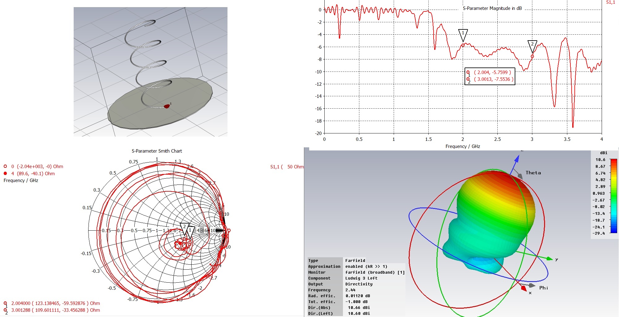
I've made a helical antenna for 2.45 GHz which consists of 130 mm diameter ground plane, a helix of 39 mm diamater with a pitch of 27 mm. The conductor is self-supporting and is 1.2 mm diameter enamled copper wire. I had 7 turns, but cut it down a bit later. The helix is in the middle of the gound plane, with an N connector about 20 mm off centre, so the outside of the helix connects to the N connector.

I've measured the input impedance on a VNA, and get nothing like the resistive 140/150 Ohms I would expect. I'm guessing with 4 turns:

31 - j 30 Ω at 2.0 GHz
20 - j 10 Ω at 3.0 GHz.

with 7 turns I had

35 - j 48 Ω at 2.0 GHz
21 - j 31 Ω at 2.45 GHz
16 - j 18 Ω at 3.0 GHz

The former I used to wind the helix was a bit different between these two setups, so the helix would have changed a bit in diameter and pitch.

But no matter what I try, a sweep of the helix over the 2-3 GHz range show it is is nowhere near resonance, and sitting towards the bottom left of a Smith chart, rather than to right of centre as I'd expect with the theoretical 140 of so Ohms.

As far as I'm aware, the dimensions are not critical, so whilst I don't claim this helix has exactly the dimensions I want, the fact the real part of the input impedance is off by a factor of about 6 is a bit worrying.

I've tried calibrating the VNA using three different cables, using both ports. I get basically the same result each time. The short/open/load were connected directly to the end of the cable when calibrating the VNA, so the N connector on the cable should measure the impedance at the N connector on the ground plane, where it was directly attached. (Obviously if I had a length of cable, I might expect this to change the impedance

I've checked the VNA (an HP one) reads basically 0.0 with a short, infinity with an open and 50 Ohms with a load. So the VNA seems to be working ok.

Any ideas?
 

Thank you.

Whilst the articles are intersting, most/all of this is in the 3rd edition of Kraus's Antennas book. The triangular shapped matching section shown in the first is intersting, though its not clear how one would calculate the size. Kraus used a wider strap for the first quarter wave to transform the impedance. You can calculate the required width/height for that.

But what is bugging me is why the impredance I'm measuring on the VNA is so far from 140 Ohms. When I first put this on the VNA, it was in SWR mode. I was not surprised the SWR was around 2.5~3:1, since I was expecting that, as the helix impedance should be nearly 3 x 50 Ohms. But then to measure the impedance and find it is well away makes no sense to me.

What is perhaps interesting is that if I calibrate the VNA, then put on a chassis mount N connector on the end of the cable, with the N connector on a ground plane, the impedance measured is about 5 - j 28 Ohms @ 2.45 GHz. If there is no groundplane, then it is about 5 - j 31 Ohms @ 2.45 GHz. It looks like the chassis mount N connector is having more effect than I'd expected. I wonder if it's possible to use the data on the N connector + ground plane in some sensible way to allow measurements of the actual helix to be made.

My aim is to design a matching network. Sure I can find one on the web, but I want to measure the helix, then design the matching network, rather than cobble something together that works, but nobody knows how exactly. I've seen too many antenna designs in commerical places where nobody knows how they actually work. Some I suspect work very poorly, but all anyone seems to care about is if the SWR is reasonable. I'm hoping to do a bit better than that with the VNA.

This is the highest frequency I have ever really designed an antenna for and measured the properties. Obviously things you can get away with at 100 MHz don't work at 2.4 GHz.

Deborah
 

My practical experience in design Mfg is 1GHz but I have used many helix single , tri and quad helix in the UHF band back in the 70's at the CHurchill NRC Rocket research telemetry station.. Imagine a small house with wall to wall racks floor to ceiling for all the telemetry equipment. MY lab at Magellan Aero (nee Bristol Aerospace) was pretty decent with a hundred or so racks of equipment from precision sig gen, SA, counters and receivers for FM-PM-AM SSB digital PCM, analog and FM-FM . My 1st antenna design was a coiled dipole that spun out when the nose cone was ejected. Fascinating to watch the spin table and squib test and see it work in the lab.

Of course you will get more gain with a parabolic dish and more turns but then the precision of the turns becomes exponentially more difficult with more turns to achieve a high Q. I was reminded of this when a friend was designing a UHF helical notch filter in a can for shunt interference during the early days of jammed pay TV. Much high Q's than an open loop coax, but much more critical to tune.

I would suggest you start with the classic 4 turn 12.5deg helix on a parabolic dish. Make sure it is pointing where no reflections will occur, as these are out of phase and your return loss will suffer. ( but great remote intrusion motion sensor with a directional coupler to detect with a hot-carrier diode to make an alarm system ;))

Then try a 5 turn 10 deg then a 6 turn 8 deg. and then 6 turn 12 deg.
YOu may have difficult getting a good plastic form to wind the coils and hold them in place while the form is removed. If kept in place, then you need to compensate for dielectric constant. As you know any dielectric near the coils will lower the centre frequency and if lossy like cheap tape it will reduce Q significantly.. microwave proof "Saran wrap" may work for low loss but plan on designing for a higher freq. or factor the dielectric permittivity to be ~3. Even epoxy resin core will do the same.. so you need good stuff like GETEK with a 10x lower loss tangent or better GETEK 2 fiberglass epoxy panel from GE as a sample or a decent PWB fab shop.. Then heat and mold to desired shape for forming and holding the coil.
 

At 2-3 GHz can even small additions such as an N-connector affect measured result, if not included in total VNA calibration.
With incorrect reading even before actual dut is connected, is it a bit hard to say anything about measured results.
For calibration of a HP VNA at these frequencies, check how I do **broken link removed**.
If you want to transform impedance from 140 to 50 Ohm with a quarter wave stub on a Helix, calculate it as a ~84 Ohm transmission line over ground.
I do normally not calculate these kind of transformers, I start with 10 mm wide cu tape, 30 mm long, and add more tape width until it looks good.

Of course I can calculate the length of λ/4 line to transform 140 Ω to 50 Ω, but I'm starting from the point of knowing the impedance of the helix is 140 Ω. But how would I measure that impedance?

BTW, I'n not convinced the optimal transmission line is of impedance sqrt(50*140). I believe its possible to increase bandwidth by tapering that impedance, which is easy to do with copper strip - less easy with coaxial cable.
 

If not very used with how your N-connectors behave at these frequencies, do I not recommend to include it at all if you really want to measure antenna impedance and nothing else. A N-connector is a rather big thing with lengths that can be complicated to compensate for.
I do this kind of stuff every day and have no problems. I propose that you calibrate VNA, including a thin coax cable. Check that calibration still is correct with the coax soldered at antenna ground plane and first then connect the antenna and nothing else.
Adjusting shape of the transmission line to something triangular can increase bandwidth, yes, but a cost of total gain at center frequency if this line also is a part of the antenna. As opposite, you can make the transmission line entirely at ground plane, allowing you to keep each turn on antenna more uniform, for best directivity and gain.
 

As I said before standard FR4 or G10 is lossy and poor for loss tangent but all fiberglass is called this, so make sure yours has a low loss tangent as I am sure these guys have done.
It was called G10 before the Fire Retardant V4 UL spec was created and G10 is outdated really, yet that is what this company still calls it.
YOur antenna at 3GHz will be twice the scale size as this one which has 10 precision wrapped turns.

Screen shot 2012-06-19 at 4.24.48 PM.PNG Note this one only gets <12dB gain with a flat radiator and uses an N connector on a groundplane baseplate.

What you want is something like HE-0100-10 10 turn which is not listed.

Screen shot 2012-06-19 at 4.30.17 PM.PNG
https://www.ramayes.com/Data Files/TMC Design/TMC Design Helical Antennas.pdf

N connectors are OK when you want to pump 200Watts thru them, otherwise any miniature high quality SM connector may work if rated for >15dB RL @ 3GHz
 

Sqrt (Z1*Z2) is the correct answer. My question is how did you build it? THere must be something wrong in the realization.,

Sqrt(Z1*Z2) works perfectly at a single frequency. Obviously if you change frequency it becomes less perfect.

I think tapering the line can reduce the effect of the frequency change. I believe I read somewhere that an exponential taper can provide improved bandwidth. I'm not sure if that is only true if done over a long length - not just a quarter wave. I can't provide any reference or proof, but I doubt a single impedance gives optimal bandwidth even when only a quarter wave long. It's quite possible that a line that starts at Z1, tapers in some way to Z2 will provide a better bandwidth.

The strucure is basically as I described at the start of the thread - if you feel I have overlooked something important, please let me know. Initially I soldered the wire to the centre of the N connector, so first the wire went at right angles to the ground plane before curving. I later changed it to wrap the wire around the centre pin, so the wire comes out parallel to the ground plane about 3 mm above it (from memory).

The thing is small changes to the geometry are not showing much change in S11 on the analyser. I think the fact the VNA shows nothing like an open-circuit when the N connector has no helix on it, suggests its a calibration problem to me. I might as a quick test try to do a calibration without using the standard cal kit, but use the open N connector on the groundplane as an open, and then use create a short there for the short.

It is self-supporting, which is not ideal, but this was only for a test in a lab. The weight of the copper wire means it does not keep perfect shape, but S11 does not appear to depend too much on the geometry. S11 does not change much if the helix is compressed or extended a bit. But Kraus has stated many times the antenna is not critical.

I've made a couple of different helixes using the same N connector and ground plane. S11 is quite similar in each case. I don't have my lab notes in front of me, but the Smith Chart display appears to be in about the same position each time.

BTW, we have some resistive loads which are not 50 Ohms - one is 60 Ohms, another 73, another 100 Ohms etc. All of these read correctly once the VNA is calibrated. But of course these are all connected in the same place as the calibration standards are, whereas the helix is connected to a chassis mount N connector.
 

I would prefer you consider a splitter and run the splitter differential 100Ω to 50Ω or similar custom splitter with impedance transformer coil inside single ended. Perhaps modify a DC-16 to run as an Z transformer and use the tap for Return loss measurements.

Transform the impedance ratio by changing the turns ratio.

https://www.minicircuits.com/pdfs/news/F396.pdf

Of course this requires some knowledge on how DC's and Splitters work and to make them work up to 3GHz
6GHz costs about $600. but 3GHz is much easier.
 
Last edited:

If not very used with how your N-connectors behave at these frequencies, do I not recommend to include it at all if you really want to measure antenna impedance and nothing else. A N-connector is a rather big thing with lengths that can be complicated to compensate for.
I do this kind of stuff every day and have no problems. I propose that you calibrate VNA, including a thin coax cable. Check that calibration still is correct with the coax soldered at antenna ground plane and first then connect the antenna and nothing else.
Adjusting shape of the transmission line to something triangular can increase bandwidth, yes, but a cost of total gain at center frequency if this line also is a part of the antenna. As opposite, you can make the transmission line entirely at ground plane, allowing you to keep each turn on antenna more uniform, for best directivity and gain.

I don't have anything other than an N cal kit, so if I was to put an SMA connector rather than an N connector, I would have no way to calibrate the analyser.

I might have no option other than to assume the antenna is about 140 Ohms, design a matching circuit, then use the VNA as a glorified SWR meter to optimize the matching circuit. If I build two like that, and measure decent gain, that might be the best I can do.

What I find odd is that looking Smith Chart, it would appear (from memory), I woud need to add an electrical length of about 20% of a wavelength to get the effect I see. I don't think the N connector is that long, but I should check this. There is a dielectric in there, so electrically it is longer than it is physically.
 

If you connect to a DC-16 or DC-24 you can get higher bandwidth and then get Return loss without a VNA using a hot carrier diode adapter.. after you calibrate it with the VNA.
Impedance transformer using similar wire must be wrapped exactly as they did but with one less turn or one more turn depending which side is easier.

https://www.minicircuits.com/pdfs/ZABDC20-322H+.pdf oops wrong one.. this is a microstrip version.
 
Last edited:

I don't have anything other than an N cal kit, so if I was to put an SMA connector rather than an N connector, I would have no way to calibrate the analyser.
No, you do not even need a SMA connector, and should avoid it if you is able to follow the instructions at www.antune.net how to do a correct calibration. I do get correct result for this type of measurement, using same tools as you. If you get different result, you do something wrong or have faulty equipment!
If I have problem with my measurement results (it happens) I try to reduce any thing that can affect the measurement. That includes anything in the environment that not is antenna or ground plane. For calibration do I use a 0402 50 Ohm SMD resistor and a soldered shortcut placed at exact point where correct measurement point is.
As I do a lot of this type of measurements is the most common problem due to too much bended and worn out semi rigid coaxial test cables and partly broken cables can give very irritating intermittent problems.
If you not want to look at the VNA as a tool that you not is able to use correctly:
1. Remove that N-connector and any else junk, as a 1:st step to find your problem in a systematical way.
2. Do a in place calibration for a low loss coaxial cable as the only thing, well soldered at ground plane.
3. Double check short (I use a sharp knife).
4. Double check open (remove knife).
5. Verify result with reactive load (SMD L and C with reasonable values relative your frequency). If measured values are way off, is it useless to continue to 6. Go back to 1.
6. Connect antenna at same spot as you did verify the calibration. Spot size is something +/- 1 mm, not +/- 10 mm.
It is not harder then that.
If I was in your situation, and after have done above and still not get expected result, do not change anything, just unsolder antenna wire from coaxial cable center wire and replace it with a vertical 30 mm wire. If you then not can measure correct complex impedance for a rather ideal quarter wave, start search backwards by replacing everything.

A not uncommon measurement problem is partly faulty N and SMA connectors due to misuse. In worst case can port connectors in the VNA or calibration kit be faulty. They can still seem to work correct at other frequencies. Here are some examples:
**broken link removed**
 
Last edited:

I assume "VNA (an HP one) reads basically 0.0 with a short, infinity with an open and 50 Ohms with a load" was over the entire range of f right? So return loss was >15dB over 2~3 GHz range right on 50ohm load?

E Kafeman's improvised procedure seems good. ( I am used to 6GHz Anritsu with 60 dB return loss and 0.01dB insertion loss after calibration.) So if calibration is ok and 1/4 wave antenna is ok, then it must be related to the mechanical details of your feed and/or the dielectric loss of the medium. Again I would start with a simple 4 turn helix.
 

Hey all :)

I couldn't resist the temptation to throw your antenna in the simulator (CST) and see if that provided any additional insight... your original intuition was spot on there, DeboraHarry :) Must dash, so I'll leave you to ponder - good luck!


(The 'ringing' observed in S11 and the regions where S11 > 0dB are due to the restrictions I imposed on the numerical precision to reduce the simulation time. I'd expect the underlying trend to still be accurate/indicative).
 
Last edited:

Status
Not open for further replies.

Part and Inventory Search

Welcome to EDABoard.com

Sponsor

Back
Top