Continue to Site

Welcome to EDAboard.com

Welcome to our site! EDAboard.com is an international Electronics Discussion Forum focused on EDA software, circuits, schematics, books, theory, papers, asic, pld, 8051, DSP, Network, RF, Analog Design, PCB, Service Manuals... and a whole lot more! To participate you need to register. Registration is free. Click here to register now.

Differtial amplifier simulation with AC signals.

Status
Not open for further replies.

sys_eng

Full Member level 4
Joined
Aug 3, 2016
Messages
193
Helped
0
Reputation
2
Reaction score
1
Trophy points
18
Activity points
1,489
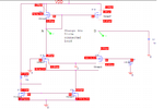
Try to simulate a simple differential amplifier ; current doesn't add up.

amp_simul5.png

My current source is 50uA

but the drain current of M16, M29 is only 3.09uA. They don't add up to 50uA.

Where are the rest of current go?
 

Re: Try to simulate a simple differential amplifier ; current doesn't add up.

Likely the current source is pulling the current through the transistor substrate diodes from ground.

In a simulation, if you use a current source, then it will do whatever it takes to generate that current.
In this case, that apparently means pulling it through the substrate diodes of the bottom transistors.

1)I thought body wouldn't conduct that Mich current.

2)instead of putting a current source there, can I use another configuration? Like current mirror? ,this way there won't be so much current through the transistor body.

3)if I use a 10k resistor replacing the current source, the current through resistor is only 6.5pA. Do you think it's better?
 

Re: Try to simulate a simple differential amplifier ; current doesn't add up.

1) It's a simulation. There's no limit as to how much current the body can carry.

2) Yes a current mirror is often what's used to generate a constant-current in an IC.

3) 6.5pA is way too low. Try connecting the resistor to a few volts negative voltage.
 

Re: Try to simulate a simple differential amplifier ; current doesn't add up.

You didn't consider that an ideal current source can source power and thus pull the diff pair common source node below ground, forward biasing the MOSFET substrates with the shown results.

In other words, the circuit bias point is totally flawed. Furthermore, the simulation circuit doesn't model a real circuit which can't have current sources with negative voltage drop.
 

Re: Try to simulate a simple differential amplifier ; current doesn't add up.

View attachment 139717

My current source is 50uA

but the drain current of M16, M29 is only 3.09uA. They don't add up to 50uA.

Where are the rest of current go?

You're using ideal current source and Vgs can be anywhere-even negative- so this set-up won't work.
Connect a high value resistor in parallel to Current Source ( for instance 22K Ohm )
 

Re: Try to simulate a simple differential amplifier ; current doesn't add up.

Well since everybody says an ideal current source is not good for simulation then I use a current mirror as such.

The left side is generating 66.67uA, not bad but the right side, M14 only having 6.581 pA. The current mirror is not working , unable to mirror. Those two transistors in the current mirror are the same.


amp_simul6.png
 

Re: Try to simulate a simple differential amplifier ; current doesn't add up.

how to increase the current on the right side of current mirror. pA is too small for the differential amplifier. this referring to the diagram above.
 

Re: Try to simulate a simple differential amplifier ; current doesn't add up.

how to increase the current on the right side of current mirror. pA is too small for the differential amplifier. this referring to the diagram above.

Is your Current Mirror working standalone ?? I mean, if you connect the second MOS to VDD directly, does it work ??
 

Re: Try to simulate a simple differential amplifier ; current doesn't add up.

First point, you have solved the problem addressed in the question title, no forward biased substrate junction and currents are "adding up" as expected.

Secondly you are continuing what you already did in the previous thread https://www.edaboard.com/showthread.php?t=369095

Overloading the differential pair with 1.5V differential input and wondering why some are turned fully off, while others are turned with zero Vds because the capacitive load can't sink static current. That's how switch circuits work.
 

Re: Try to simulate a simple differential amplifier ; current doesn't add up.

Is your Current Mirror working standalone ?? I mean, if you connect the second MOS to VDD directly, does it work ??

If I disconnect like that then it works (current mirror). It doesn't work when hooked up to diff amp.

- - - Updated - - -

First point, you have solved the problem addressed in the question title, no forward biased substrate junction and currents are "adding up" as expected.

Secondly you are continuing what you already did in the previous thread https://www.edaboard.com/showthread.php?t=369095

Overloading the differential pair with 1.5V differential input and wondering why some are turned fully off, while others are turned with zero Vds because the capacitive load can't sink static current. That's how switch circuits work.

I don't have capacitive load on this on. The diff amp still drawing only 6.581pA, what's the reason?
amp_simul7.png
 

Re: Try to simulate a simple differential amplifier ; current doesn't add up.

I don't have capacitive load on this on. The diff amp still drawing only 6.581pA, what's the reason?
View attachment 139744

Because M16 has no bias voltage (Vgs) so the drain does not draw any current.Unfortunately you connected the upper current mirror that is controlled by M24 that is connected to M16 in series.So briefly, M24 controls the mirror current and when its drain current is zero due to M16, the other current on the second branch compulsorily won't source any current.
Bias M16 with a voltage that is greater than Vt.
 

Re: Try to simulate a simple differential amplifier ; current doesn't add up.

Because M16 has no bias voltage (Vgs) so the drain does not draw any current.Unfortunately you connected the upper current mirror that is controlled by M24 that is connected to M16 in series.So briefly, M24 controls the mirror current and when its drain current is zero due to M16, the other current on the second branch compulsorily won't source any current.
Bias M16 with a voltage that is greater than Vt.

According to text book, differential amp is when one side is on (M29) and the another side is off (M16).
One side should conduct all the current and the other side shouldn't conduct any. right?

Are you saying both M29 and M16 should be biased to be turned on and both sides of Diff amp are on?
 

Re: Try to simulate a simple differential amplifier ; current doesn't add up.

According to text book, {blah blah}

You can't expect this circuit to work as a small signal
amplifier when you have jacked the input with a large
signal. Determine when the input linear region is (once
you have fixed common mode range / biasing issues
and then try simulating as an amplifier. What you've
got here is a poor quality comparator, way overdriven.

You can't expect it to work when the left side of the
pair has zero Vgs and cuts out the PMOS mirror master.
The NMOS sink can't pull any current through the left
side, and the right side is buried (you do not see this
because you do not display the "output" node voltage.

Your NMOS mirror is run at way too high a gate voltage
(trying to stuff more current down a nonfunctional
diff pair, I expect) - back off, a lot.

Try putting the inputs at about 2V common mode with
(say) a 10mV sine difference.
 

Re: Try to simulate a simple differential amplifier ; current doesn't add up.

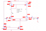
You can see the reason for "no current" in the present circuit by looking at the node voltages.

I don't have capacitive load on this on. The diff amp still drawing only 6.581pA, what's the reason?
You changed capacitive load into no load, the effect is the same, the amplifier can't source output current. If you connect a resistive load biased to Vdd/2, you get current.
 

Re: Try to simulate a simple differential amplifier ; current doesn't add up.

You can't expect this circuit to work as a small signal
amplifier when you have jacked the input with a large
signal. Determine when the input linear region is (once
you have fixed common mode range / biasing issues
and then try simulating as an amplifier. What you've
got here is a poor quality comparator, way overdriven.

You can't expect it to work when the left side of the
pair has zero Vgs and cuts out the PMOS mirror master.
The NMOS sink can't pull any current through the left
side, and the right side is buried (you do not see this
because you do not display the "output" node voltage.

Your NMOS mirror is run at way too high a gate voltage
(trying to stuff more current down a nonfunctional
diff pair, I expect) - back off, a lot.

Try putting the inputs at about 2V common mode with
(say) a 10mV sine difference.


Ok, I hooked up circuit with common mode of 2V DC on both sides and a diff signal of AC of 30mV on the right side.
Right now I can see current of 16.24uA, but they are the same on both sides. I thought some differences due to diff AC signal.
amp_simul8.png

however, I do not see any AC signal being amplified at the output , at point A or point B. Here's the plot.
plot.png
I have diff signal AC at the right side input
 
Last edited:

Re: Try to simulate a simple differential amplifier ; current doesn't add up.

There's something wrong about the results, no way
should those two drain nodes be exactly 2.00V, both.
You might want to look at the "guts" of those MbreakN
symbols and be sure they are not able to short G to D
(or, some implicit net naming mess-up?).

Annotating the voltages might help your debug.

Keep in mind those 2V at the drain are only DC bias voltage. It doesn't include AC signals.
both drain nodes are same because both transistors got biased the same at gate of 2V.
 

Here's my setup. a common mode of 2V at the inputs of M16, M29. and AC differential signal at M29
amp_simul10.png


and the output wave form at the point A, B. output nodes.

amp_simul9.png

Does this look OK? any comments welcomed.
 

Re: Try to simulate a simple differential amplifier ; current doesn't add up.

I do not believe your "because" logic, and find the
Vg=Vd=2.00V just too cute to be credible. But I'll
leave the further debug, to you.
 

Status
Not open for further replies.

Part and Inventory Search

Welcome to EDABoard.com

Sponsor

Back
Top