Continue to Site

Welcome to EDAboard.com

Welcome to our site! EDAboard.com is an international Electronics Discussion Forum focused on EDA software, circuits, schematics, books, theory, papers, asic, pld, 8051, DSP, Network, RF, Analog Design, PCB, Service Manuals... and a whole lot more! To participate you need to register. Registration is free. Click here to register now.

differential voltage feedback

Status
Not open for further replies.

zizi110

Member level 1
Joined
Jun 24, 2013
Messages
41
Helped
0
Reputation
0
Reaction score
0
Trophy points
6
Activity points
313
Hi guys,
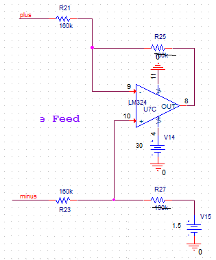
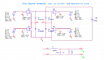
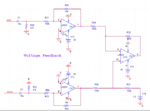
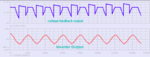
I have a full-bridge dc-ac converter that VDC= 24v. for having feedback voltage of inverter output ; my supervisor said that i can use this circuit ( below) but when i simulate it by Pspice ,the simulation result is not good .can anyone help please?
 

Attachments

  • 1a.png
    1a.png
    17.6 KB · Views: 70
  • 2aa.png
    2aa.png
    21 KB · Views: 75
  • 3d.png
    3d.png
    17.4 KB · Views: 68

According to the circuit topology, all amplifiers need bipolar power supplies, e.g. +/- 15V.
 
thanks FvM,
you are right , by doing so , the waveforms becomes as expected :)
but is there any way that i can use it in single supply mode?
 

You establish a false "earth", by putting a divider across your 24V line, to give +12V with reference to the 24V negative terminal. This line must have a low impedance (big decoupling capacitor). Then your old +Vcc lines become +12V wrt the "earth" and the old DC 0V connections become -12V wrt the "earth". This does put an offset of +12V on all your signal lines which have to be sorted out.
Frank
 

Hi chuckey ,
sorry i can't understand , did you mean i must connect vdc in this manner:
dddddd.png
 

thanks FvM,
i simulate it and it is ok, but why?
why the first stage is not necessary?
 

The first stage doesn't serve a meaningful purpose in your design. Would be different with non-inverted buffers or a differential stage as used in the classical three OP instrumentation amplifier, usefull if you want high input impedance.

I forgot to mention that + and - inputs have to be switched for the single OP circuit.

The original circuit lacks of a suitable bias. It could be fixed in a different way, but you need to connect the non-inverting OP inputs to a positive voltage instead of ground. But as said, this would be purposeless effort.
 

Status
Not open for further replies.

Similar threads

Part and Inventory Search

Welcome to EDABoard.com

Sponsor

Back
Top