bhushan233k
Junior Member level 2
dear friends
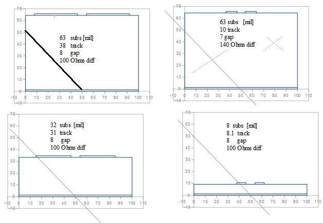
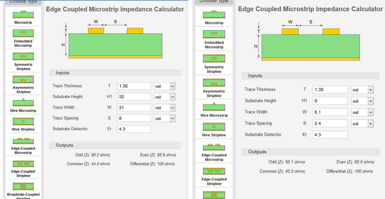
I want to route 100 ohm differential pairs of LAN
on two layer pcb ( 1.6mm pcb thickness ) with 8 mil trace width, 8 mil trace spacing , 1.4 mil trace thickness.(dielectric constant Dk=4.3 as fr4 material with 1.6 mm is used)
can anybody help me how to calculate 100 ohm impedance with above data......