Continue to Site

Welcome to EDAboard.com

Welcome to our site! EDAboard.com is an international Electronics Discussion Forum focused on EDA software, circuits, schematics, books, theory, papers, asic, pld, 8051, DSP, Network, RF, Analog Design, PCB, Service Manuals... and a whole lot more! To participate you need to register. Registration is free. Click here to register now.

Differential pair input

Status
Not open for further replies.

edinburghtech

Junior Member level 2
Joined
Jan 28, 2012
Messages
21
Helped
0
Reputation
0
Reaction score
0
Trophy points
1,281
Visit site
Activity points
1,467
Hi

I am designing a current steering DAC in which a current cell constitutes of a current source, cascode and differential pair. Digital input comes to the differential pair which causes the current to be channeled through either of the branches. At the moment the input of the differential pair swings from 0 to Vdd (3.3V). I would like to reduce this swing to 1V. Can someone please tell me a circuit topology which can convert 0 - 3.3V swing to 1.15 - 2.15 V swing

Thanks
Tech
 

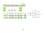
You could use an opAmp for that, but you need a negative reference voltage (selectable; I used -3.3V), see below:
 

I am designing a current steering DAC in which a current cell constitutes of a current source, cascode and differential pair. Digital input comes to the differential pair which causes the current to be channeled through either of the branches. At the moment the input of the differential pair swings from 0 to Vdd (3.3V). I would like to reduce this swing to 1V. Can someone please tell me a circuit topology which can convert 0 - 3.3V swing to 1.15 - 2.15 V swing.

Your post raises quite a number of questions: May I ask why you would want to do this? And does the voltage range need to be exactly the same in all process corners and for the whole temperature range, or do you need something that tracks? Finally, if you need precise limits, is a reference voltage available?

Slainte!
hanspi
 

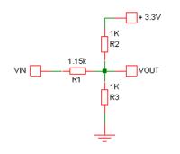
Why can't you just use a simple resistive divider like this?


This can't be used because it uses a lot of static power compared to other types of voltage-level shifters and requires the digital stage before to have a very strong buffer at the output. We are, after all, discussing a current-steering DAC, so whatever you guys propose will go onto the chip at least as many times as the DAC has bits.

Slainte!
H
 

This can't be used because it uses a lot of static power...
...and requires the digital stage before to have a very strong buffer at the output.
Fair enough. However exactly the same argument can be made against the kind of circuit proposed by erikl. Bear in mind that actual resistor values in either circuit can be scaled to taste.

For example, if you increase the resistor values in my circuit 100-fold, the static power consumption is only about 55uW. Is that still too high? Would the input impedance of over 150K still be too difficult a load for the preceding digital stage to drive?

....compared to other types of voltage-level shifters...
Can you suggest any kind of voltage-level shifter that does not have any significant static power consumption?
 
Hi godfrey,

yes, erikl's circuit suffers from the same problem.

If you increase the resistors to 100k each, even a 100fF capacitor at the diff-pair input will increase the time constant to 5 ns, resulting in a not so steep slope of the diff-pair control signal. If that slope is not so steep, then the noise from your resistors will randonly shift the switching time, resulting in noise on the analog signal, equivalent to clock jitter. It would be hard to calculate this thoroughly, but my estimate is that the jitter may well be in the range of 0.5ns, and if you want a 10-bit-DAC, then the minimum sample time gets 2^10*0.5ns = 500ns, limiting the operating speed to 2MHz.

Concerning other level-shifting ideas, I'd rather first hear edinburghtech's explanation on why she or he wants 1.15 - 2.15 V swing. I find that quite strange as it will probably make the CS DAC less precise.

Slainte!
H
 

Status
Not open for further replies.

Part and Inventory Search

Welcome to EDABoard.com

Sponsor

Back
Top