Continue to Site

Welcome to EDAboard.com

Welcome to our site! EDAboard.com is an international Electronics Discussion Forum focused on EDA software, circuits, schematics, books, theory, papers, asic, pld, 8051, DSP, Network, RF, Analog Design, PCB, Service Manuals... and a whole lot more! To participate you need to register. Registration is free. Click here to register now.

Differential High voltage measurement

Status
Not open for further replies.

Amr Wael

Member level 5
Joined
Jul 13, 2020
Messages
84
Helped
0
Reputation
0
Reaction score
1
Trophy points
8
Activity points
852
Hello ,
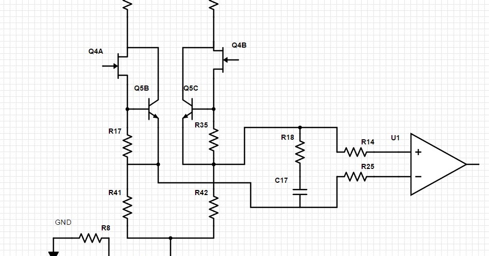
I am trying to measure differential high voltage signal , actually not very high it could reach 500V (+/-250) down to 10V. I designed a PCB with resistive dividers to attenuate the signal and then used voltage follower stage , difference opamps and error adjustment stage.\
After that I found out that I need over and under votlage protection circuits so the PCB became very expensive. Are there any other techniques for measuring high voltage differential signal for frequencies starting from DC to 300 KHz ?
Thank you very much in advance!
 

Possiblity, eg. modify this design -


Regards, Dana.
 

Hi,

A voltage divider may be sufficient, since it divides down high voltage to safe voltage. It depends against what "high voltage" you want to protect.

For the circuit: an instrumentation amplifier is a good way.
Often the output of the Opamp goes to an ADC ... if so, there are ADC with differential input, simplifying input stage.

Klaus
 

Page 6-16 of attached.


Regards, Dana.
 

Attachments

  • designers-guide-instrument-amps-complete.pdf
    3.8 MB · Views: 155

High voltage, high bandwidth voltage dividers need capacitive compensation, ususally with individual adjustment, not particularly due to amplifier input capacitance but to account for the parasitic resistor parallel capacitance. Intended 300 kHz isn't really high bandwidth, you may come away without compensation at all, or at least with fixed compensation. The need for adjustment is specifically imposed if you want to achieve good high frequency CM attentuation.

PCB layout of the divider network plays however an important role.
 

Status
Not open for further replies.

Similar threads

Part and Inventory Search

Welcome to EDABoard.com

Sponsor

Back
Top