darkfeffy
Newbie level 4
Hi guys,
I know this should be obvious, but there's something I am just NOT getting.
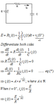
Imagine a simple series RC circuit with a DC source as shown in the attachment. As can be seen from the picture, I have solved the differential equation in capacitor current in the time domain. In order to be able to solve the problem, I have assumed that dE/dt = 0 as this is a dc source.
What I wish to know is why can't I take the Laplace transform of both sides of the equation (*)? I know that L(0) = 0, so this would give a bogus equation (i.e. I(s) = 0, which is wrong). But if my equation (*) is right, then why can't I use the laplace transform of both sides at this point?
From textbooks, I read that the DC source is considered as a step input, thus in the Laplace domain, this would be E/s. So again, what is wrong with equation (*)? And why do I get the right answer at the end?
Again, as I said, I think this should be obvious, so please don't hesitate to point out trivialities.
Thanks for your understanding.
e.
I know this should be obvious, but there's something I am just NOT getting.
Imagine a simple series RC circuit with a DC source as shown in the attachment. As can be seen from the picture, I have solved the differential equation in capacitor current in the time domain. In order to be able to solve the problem, I have assumed that dE/dt = 0 as this is a dc source.
What I wish to know is why can't I take the Laplace transform of both sides of the equation (*)? I know that L(0) = 0, so this would give a bogus equation (i.e. I(s) = 0, which is wrong). But if my equation (*) is right, then why can't I use the laplace transform of both sides at this point?
From textbooks, I read that the DC source is considered as a step input, thus in the Laplace domain, this would be E/s. So again, what is wrong with equation (*)? And why do I get the right answer at the end?
Again, as I said, I think this should be obvious, so please don't hesitate to point out trivialities.
Thanks for your understanding.
e.