Continue to Site

Welcome to EDAboard.com

Welcome to our site! EDAboard.com is an international Electronics Discussion Forum focused on EDA software, circuits, schematics, books, theory, papers, asic, pld, 8051, DSP, Network, RF, Analog Design, PCB, Service Manuals... and a whole lot more! To participate you need to register. Registration is free. Click here to register now.

Differential and single-ended L and Q of an inductor

Status
Not open for further replies.

Hamid.Kiumarsi

Full Member level 2
Joined
Aug 18, 2010
Messages
142
Helped
33
Reputation
66
Reaction score
31
Trophy points
1,308
Location
Japan
Activity points
2,232
Dear all

I have simulated an inductor in ADS's momentum.

For getting differential L and Q I can
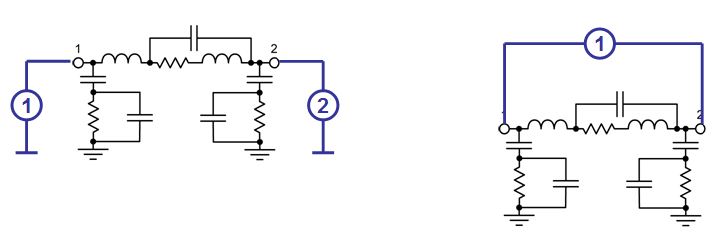
1) either use one differential port
2) or use 2 single-ended ports and then get the mixed-mode S parameters.
Both above-mentioned methods of 1 and 2 for differential L and Q give same results.

However for getting single-ended L and Q I use single-mode S parameters.

There is a slight discrepancy in L and Q of the inductor if I simulate it with differential port or single-ended ports.
My question: is this common and normal?
 

Yes, you will get different results if L and Q=Im{Y11}/Re{Y11} are calculated from the properties of port 1.

93_1320671699.jpg
 
Last edited:

I understand that those shunt R and C networks at port1 and port2 are for pads.
Why is that in your schematic, the inductor model has another L at port1 in addition to well known combination of R and L in series with shunt capacitor.
Could you be more elaborate with some equations.

And what does this different L and Q imply? With different signaling we'll achieve different L and Q?
 

I understand that those shunt R and C networks at port1 and port2 are for pads.

No, this is the coupling of the inductor to the substrate.

If you calculate Q using Y-parameters, Q=Im{Y11}/Re{Y11}, then you get the Q factor into port 1, with port 2 shorted.

And what does this different L and Q imply? With different signaling we'll achieve different L and Q?

Yes. Different substrate parasitics for different modes, so you get different results.
 

Therefore, since transformers are mostly used in differential structures, we should use differential L and Q. (correct me if I am wrong)
What if they are used only for impedance transformation?
 

Therefore, since transformers are mostly used in differential structures, we should use differential L and Q.

I tend to agree.

What I recommend to my Sonnet customers is to simulate as a two-port, so that both common and differential mode are included in the data, and then use that two-port in Cadence. This is the safest method, in my opinion. Doing only the differential case might by too optimistic if the actual circuit has some common mode component.
 

I am simulating with Momentum. Since I am using patterned ground shield, I can not use ///GND/// of Momentum.
Also using ground reference ports has its own problems. Therefore I am using differential ports and I will miss common-mode data.
If you have experience in simulating an inductor (with patterned ground shield) as a two-port inductor using Momentum, please advise.
 

If you have experience in simulating an inductor (with patterned ground shield) as a two-port inductor using Momentum, please advise.

Sorry, I have no idea how to solve the Momentum port issues. I use Sonnet for all my RFIC work.
 

Status
Not open for further replies.

Part and Inventory Search

Welcome to EDABoard.com

Sponsor

Back
Top