Continue to Site

Welcome to EDAboard.com

Welcome to our site! EDAboard.com is an international Electronics Discussion Forum focused on EDA software, circuits, schematics, books, theory, papers, asic, pld, 8051, DSP, Network, RF, Analog Design, PCB, Service Manuals... and a whole lot more! To participate you need to register. Registration is free. Click here to register now.

Differential amplifier PMOS/NMOS Current source

Status
Not open for further replies.

sherif96

Member level 4
Joined
Feb 22, 2018
Messages
77
Helped
0
Reputation
0
Reaction score
0
Trophy points
6
Activity points
732
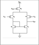
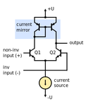
It might be a pretty basic question, but what is the difference between an NMOS current source driving a differential pair and a PMOS current source driving a differential pair,I am trying to find out which would give a larger output swing and why, so what would be the difference in regards to maximum output voltage and minimum output voltage? if I have a circuit as attached, what would be the max output voltage equation for both and what would be the minimum? - let the current source in the second attachment be a NMOS transistor
 

Attachments

  • OTA PMOS current source.png
    OTA PMOS current source.png
    13.7 KB · Views: 724
  • NMOS current source.png
    NMOS current source.png
    8.7 KB · Views: 824

Hi,

Sorry about this, help me, there's something that isn't completely coinciding between your text and the pictures, for me at least. e.g. I think I understand the question fully but the wording and picture contrast leads to a doubt. Again, sorry there.
Can you clarify where it should read NPN and where PNP or which part of which schematic just to be sure the question is/has been understood, please?

Useless answer: I simulated PNP input and NPN op amps exactly like those in your schematics but two-stage to compare over a year or more ago and just can't remember specifically - it would mean searching through schematics for hours to find the results I recorded - can't do that right now. I remember that one had output 0 to >mid supply, other - unsurprisingly - < mid supply to V+, both hit the rails monotonously beyond that limited input range. It was a 1.1V supply and op amp made using TUNs and TUPS and cheap resistors in simulation and on breadboard. Sorry can't be of more help.

If you sum what's in the way of the load from the supply or from ground you can get an approximation of max and min and - I think it's called something like - saturation point. Think of how you calculate a current source by subtracting voltage drop(s), or look it up, about the same in a sense. Probably a bad method but okay as rule of thumb for estimation. You can improve the swing with emitters between collector and current source collectors, I recollect - nothing to do with max/min Vout 'though.
 

If you want a differential function, the long-tail pair needs only one current source. In the basic topology it does not need a current mirror.

In fact it may be sufficient to have a plain resistor rather than a constant current source. Here is a simplest possible differential long-tail pair. Notice the ramp signal appears in the output only when it is a greater voltage than the sine.
Taking output at the emitter makes this a voltage-follower.
With modifications it can be made to apply gain, which would make it an amplifier.

simplest differential amplifier 2 NPN 1 long-tail resistor.png

If the resistor were replaced with a current source, it would not change the output in the simulation.
 

Status
Not open for further replies.

Similar threads

Part and Inventory Search

Welcome to EDABoard.com

Sponsor

Back
Top