Continue to Site

Welcome to EDAboard.com

Welcome to our site! EDAboard.com is an international Electronics Discussion Forum focused on EDA software, circuits, schematics, books, theory, papers, asic, pld, 8051, DSP, Network, RF, Analog Design, PCB, Service Manuals... and a whole lot more! To participate you need to register. Registration is free. Click here to register now.

Differential Amplifier and rail to rail issues

Status
Not open for further replies.

Hawaslsh

Full Member level 3
Joined
Mar 13, 2015
Messages
164
Helped
5
Reputation
10
Reaction score
7
Trophy points
1,298
Location
Washington DC, USA
Activity points
3,422
Edit: OMG: Rail to Rail, not rain to rain!!!!!!!

Hello,
1604351870227.png

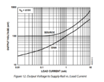
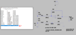
I am working to design a current limiting circuit for a power supply board. In order to monitor the current, I planning on monitoring the voltage across a 0.1 Ohm current shunt using a differential amplifier. The circuit above shows what I have simulated. The left side of the circuit shows the current shunt and a current limiting resistor setting the 3A limit. This setup should give me an output ~ 300 mV, but the real output is ~800mV. This is definitely a rail issue due to the cheapo LM358 but I had a few questions about this.
1604352075711.png

I adjusted the supply for the op-amp to be well above the voltages on either side of the current shunt, however, the output still sat at the 800mV. why didn't this solve the problem?
1604352327290.png

Further confusing me: I added gain to the circuit with the increased supply voltage circuit, and it worked? I got the expected 300mV * 10 = 3V ?

Most of these issues can be solved with a better rail to rail op-amp, but clearly I am missing something fundamental to op-amps here.
Thanks for any and all help,
Sami
 
Hi,

Common mode input voltage range of LM358 is V-1.5V.
--> Use an Opamp with common mode input voltage range up to V+

Klaus

Added:
Sorry, CMIVR should not be the problem here ... I'm still looking...
 

Hi,

I vote this thread best title of the year. You need a sun-to-sun op amp, it's the rain-to-rain op amp that's the problem. ;)

I had this problem recently. That difference amplifier configuration is best described as 'NRND' - a common-mode voltage that is 1/2 V1 - V2 (or V2 - V1) rides on the output signal. Besides needing matched resistors.

Changing gain is an illusory solution - try a different Vin and the output will be wrong again. I know, I wasted a few hours on the same circuit last week.

If you can, use a proper difference amplifier.
 

    Hawaslsh

    Points: 2
    Helpful Answer Positive Rating
Hi,

See TI datasheet Figure 11. Output sink current 2.5mA gives 0.8V output voltage.
To get down to 0.1V the current needs to be less than 20uA --> 100k.

But why not increase the gain to 10? 10k/100k
Then you get 3V instead of 0.3V.

Klaus
 

    Hawaslsh

    Points: 2
    Helpful Answer Positive Rating
Review datasheet figure 11, this should answer your question.

20201102_231251.jpg
 

    Hawaslsh

    Points: 2
    Helpful Answer Positive Rating
Your sense resistor appears to be close to the positive supply rail (high side). It's a region where your op amp may give non-linear readings, or give severe offset errors.

It should work better if you put the sense resistor close to ground. It could require reworking your circuit.

I think I heard there are op amps whose differential detector has P-devices instead of N-devices. It makes it easier to use a high-side sense resistor.
 

See TI datasheet Figure 11.

Review datasheet figure 11, this should answer your question.

View attachment 165331

1604384725601.png

I really don't understand the graph. From my flawed interpterion; The output is a fixed, known value, if the amp is forced to sink current. The top example has the 5V source, and the amp sinking ~300uA. From figure 11, 300uA would give a Vout close to the simulated 640mV. However, if I change the supply to be the 6.5V (to make sure i'm within the rail), the amp is still sinking current, 127uA, but its not the fixed value from figure 11?
1604384151689.png

at this point it's a learning exercise. d123 made a GREAT point, a dedicated difference amplifiers cost just as much as a rail-rail op-amp, and I wouln't need external resistors to boot. Feels like cheating simply using an IC, but it will be protecting some expensive chips down the path.
1604384551052.png

Thanks again for all the help
 

That's the main current path into the OP output. You can also read the OP output current from the operation point list.

1604388299743.png
 

Hi,

at this point it's a learning exercise. d123 made a GREAT point, a dedicated difference amplifiers cost just as much as a rail-rail op-amp, and I wouln't need external resistors to boot.

With your difference amplifier you build a "high side current sensor".

And exactly for this application there are optimized "high side current sense amplifiers". Just do an internet search.

Klaus
 

You can also read the OP output current from the operation point list.
I'm no LTspice expert, but that's what I thought I did?
1604408110713.png
 

Attachments

  • 1604413773226.png
    1604413773226.png
    61.3 KB · Views: 181
  • 1604414393199.png
    1604414393199.png
    184.2 KB · Views: 189

1604415340245.png


The CM in is not being violated for a 0 - 3A shut current, room temp, Vsupply 6V,

Keep in mind diff amp R accuracy has to be good to insure CM is rejected, otherwise
you will be amplifying that as well.


Regards, Dana.
 
Last edited:

I'm no LTspice expert, but that's what I thought I did?
Yes, you did correctly in post #7. The different circuits reveal different problems LM358. In post #1 yoe have output saturation at about 800 mV due to 1.8 mA sink current. In post #7, output current is much lower, but your are exceeding OP input common mode range with 5V supply.
 

Op-amps can be rail to rail input ( CM range ) AND/OR rail to rail output ( for light currents )

the LM358 is the same chip as the LM324 - the inputs can go to 350mV below gnd ( -350mV ), but not to positive rail,

the output can get very near gnd ( <5mV ) - esp with 100E pull down resistor on o/p pin, but not up to +ve rail ....

LF358 can have its inputs at the Vin+ rail ( but not the neg rail )

Some expensive op-amps can do input or output rail to rail - and some both ....
 

For purposes of comparison and contrast...
By operating a PNP in common-base mode, you have the high-side sense resistor causing B-E voltage to change, thus changing transistor conductivity. (This takes advantage of common-base characteristics: low input impedance, high gain.)

Illustration of simple amplifier, gain 23. Resistor values need to be tweaked in order to obtain zero-in zero-out performance.

With careful adjustment you can get by with a reduced sense resistor value. (Notice your .1 ohm value dissipates almost 1 Watt of heat when carrying 3 Amps.)

sense resis high-side measures 0-3A via common-base PNP.png
 
  • Like
Reactions: d123

    d123

    Points: 2
    Helpful Answer Positive Rating
Status
Not open for further replies.

Similar threads

Part and Inventory Search

Welcome to EDABoard.com

Sponsor

Back
Top