Continue to Site

Welcome to EDAboard.com

Welcome to our site! EDAboard.com is an international Electronics Discussion Forum focused on EDA software, circuits, schematics, books, theory, papers, asic, pld, 8051, DSP, Network, RF, Analog Design, PCB, Service Manuals... and a whole lot more! To participate you need to register. Registration is free. Click here to register now.

Different Primary Inductance value

Status
Not open for further replies.

sabu31

Advanced Member level 1
Joined
Jan 28, 2011
Messages
441
Helped
12
Reputation
24
Reaction score
13
Trophy points
1,298
Activity points
5,103
Hi all,

I am winding a U-core transformer with two configurations as shown in figure . Even though the effective turns are the same, the Primary inductance is different. What is the reason and any references for the same.
 

Attachments

  • Transformer Winding Structure.png
    Transformer Winding Structure.png
    19.2 KB · Views: 119

In the parallel configuration, the winding polarity is such that they are bucking each other (look at the flux direction of each).
Reverse the polarity to one of the windings.
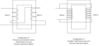
Presumed inductance values have been correctly measured, reversed winding polarity is the only way to get a lower inductance in the second configuration. The numbers indicate however a relative low coupling (about 0.63) of both windings. Can you explain the core configuration (dimensions, material, possible air gaps)?
 
One can see by inspection that the arrangement with the windings in series is 4x the inductance the arrangement with windings in //.

Ergo twice as many turns in the same direction on the core give 4x inductance .... as L prop to N^2
 

Hi,

I may be wrong...
Two x 3 turns in series on the same core gives 6 turns.
One x 6 turns should give the same inductance.

But then my understanding:
Paralleling two windings x 6 turns on the same core ... should not change the total current.
Ideally both windings carry half of the total current.
(Maybe I find the time to do some tests on this)

Thus I'm with FvM.
I expect the 2 x 6 windings are not in parallel, but in anti_parallel.
With ideal 100% coupling both inductances cancel to zero.
But with non ideal coupling it results in non_zero inductance.


Klaus
 

Let's assume inductance of 6 turn partial winding is 4x the 3 turn winding, L6 = 4*L3.
Then we get total inductance for first ( series) configuration Ls = 2*(1+k)*L3 and for second (parallel) configuration Lp = 0.5*(1+k)*4*L3 -> Lp = Ls, independent of coupling factor k

To get the reported completely different inductance values, there must be something very wrong. Possible explanations:
- wrong winding configuration, e.g. reversed winding or different number of turns
- winding short
- inappropriate measurement frequency
 

Hi all,

I put a copper tap across the transformer to make a faraday shield .

I then removed the parallel connection.
In one winding across one leg, it was observed as 204uH (at 100kHz)
In other winding across other leg, it was observed as 150uH (at 100kHz).

In one parallel configuration (which is parallel configuration). The value observed is 134uH
In other parallel configurations, it is 3uH (which proves this is anti-parallel configuration).

Now the question arises

a. Why two same turns (6 Turns) are giving different results
b. WHy 6 turns on same leg ( not considering the parallel), is having different ((204 uH and 150uH) results than 3 turns on two legs connected in series (6 Turns) (around 340uH).

The earlier measurement of 86uH was observed when no faraday shielding was there.

I am attaching photograph for your reference.

The core is amorphous metal core (UMCCC200) with
Permeability around 10k
Magnetic length Lm =27.93cm
Cross section area=7.98cm^2
 

Attachments

  • 20211014_144725.jpg
    20211014_144725.jpg
    1 MB · Views: 91
  • 20211013_174927.jpg
    20211013_174927.jpg
    1.1 MB · Views: 79

You didn't mention yet that inductance was apparently measured with secondary winding in place. In this case, I won't expect a meaningful measurement at 100 kHz, too close to secondary winding SRF. Main and leakage inductance can be better measured at 1 kHz. Another problem is the magnitude dependency of ferrous core permeability.
 

You didn't mention yet that inductance was apparently measured with secondary winding in place. In this case, I won't expect a meaningful measurement at 100 kHz, too close to secondary winding SRF. Main and leakage inductance can be better measured at 1 kHz. Another problem is the magnitude dependency of ferrous core permeability.
Hi FVM,
I measured at 1kHz and 100Khz. Its still not making much of difference. I am attaching the LCR readings for measurement at primary side (secondary open / secondary short ) at 1kHz and 100khz.

I am not able to resolve the issue of negative inductance which was discussed in earlier post, I am assuming capacitance is affecting the leakage measurement.

So what could be issue of series connection of 2 set of 3Turns having more inductance than single 6T turn connection.
 

Attachments

  • E498x395.gif
    E498x395.gif
    9.4 KB · Views: 74
  • E498x404.gif
    E498x404.gif
    9.4 KB · Views: 79
  • E498x405.gif
    E498x405.gif
    9.5 KB · Views: 82
  • E498x411.gif
    E498x411.gif
    9.5 KB · Views: 85

Thanks for reporting. I fear, the transformer behaviour is too complex to diagnose it from a distance. I'm e.g. unable to foresee the shield effect.
 

Thanks FvM for the reply. Is there any information which would be helpful.
 

Status
Not open for further replies.

Similar threads

Part and Inventory Search

Welcome to EDABoard.com

Sponsor

Back
Top