Continue to Site

Welcome to EDAboard.com

Welcome to our site! EDAboard.com is an international Electronics Discussion Forum focused on EDA software, circuits, schematics, books, theory, papers, asic, pld, 8051, DSP, Network, RF, Analog Design, PCB, Service Manuals... and a whole lot more! To participate you need to register. Registration is free. Click here to register now.

different Crystal oscillators

Status
Not open for further replies.
Please post more info. There is no way somebody can answer you without knowing to what are you referencing.
 

"The basic phenomenon behind working of a quartz crystal oscillator is the inverse piezo electric effect i.e., when electric field is applied across certain materials they start producing mechanical deformation. These mechanical deformation/movements are dependent on the elementary structure of the quartz crystal. Quartz is one of the naturally occurring materials which show the phenomena of piezo electricity, however for the purpose of resonator it is artificially developed since processing the naturally occurring quartz is difficult and costly process." **broken link removed**

What I dont understand is that If electric field has to be applied across certain materials to generate piezo electric effect then we have to have at least 3 pieces inside a Quartz Crystal ; the main piece is the crystal itself that causes the piezo electrica effect thus generating the frequency and the other 2 pieces are the anode and the cathoded that sandiwices the crystal. So based on my understanding each piece has to have its on pin sticking out from the Quartz Crystal. So why there are 2 legs? or how come?
 

That's not quite right, but close. The quartz itself does not have a connection and the two connections are not an anode and a cathode (which inplies a polarity) but electrodes bonded to the quartz to induce movement and pick up a voltage as the crystal relaxes. The resonance is due to the mechanical properties and size of the quartz, applying a voltage across the electrodes causes a physical change in the crystal lattice and on removal of the voltage the lattice reverts to it's original position, releasing a small volatge as it does so. The critical thing is that it will only do this at a particular frequency. You can reverse the connections to a quartz crystal and it will work exactly the same.

Three pin devices are usually resonators, they work in the same way but use ceramic materials instead of quartz and are not as temperature stable. They also have lower 'Q' meaning they can be persuaded to resonate over a wider range around their design frequency. They also have two pins but as in many case they are used in microcontroller applications where the frequency may not need to be very accurate but the cost must be as low as possible. As most microcontrollers have built in oscillators that rely on an external resonantor or crystal and also need loading capacitors from each end of them, some manufacturers build the capacitors inside the resonator body, bringing their common connection (normally connected to ground) to a third pin. It's a cost saving convenience to designers.

I've attached a picture of a glass cased quartz crystal that will help to explain. Sorry it isn't very clear but it's a small crystal and taken on a mobile phone! You can just see the circular disc of quartz, almost touching the glass walls, the lighter parts are the electrodes, the back one is visible through the quartz. you can also see the tiny solder jonts where the wires are bonded to the electrodes.

Brian.
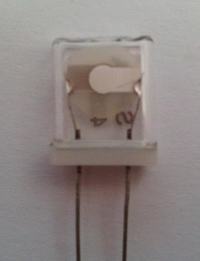


Thank you Brain. That made more sense. Just for the sake of clearification; If I supply one of Crystal oscillator's leg with 5VDC constant signal the Crystal oscillator will not function, is it right? The DC power must be a square wave/or any other type of wave form in order to get the Crystal oscillators generates clocking signal. That is what I understood.
 

You contradict yourself by saying 5VDC constant signal. Anything DC cannot also be a signal!

The important property of quartz crystal or resonator is that it's impedance changes suddenly at resonant frequency. They actually have a peak and dip in impedance very close together in frequency and this is used either in series or parallel with a positive feedback path in an amplifier to make it prefer that frequency to oscillate at. Both quartz and ceramic resonators have other uses than in oscillators, they can be used in series or parallel to pass or reject particular frequencies. For example, in radio receivers they are commonly used to create a narrow frequency window so that only desired signal pass through and others are rejected.

Brian.

I should've said feeding the quartz crystal by Battery source rather than 5VDC constant signal. Thank you for spending time and answering the questions however I am still not clear about how 2 pin crystal ossilators are triggered to generate certain frequencies and how this frequencies are given to other components to use. If there were 3 pins it would ve made sense but 2 pins, just doesn't.
 

The quartz crystal (or ceramic resonator) cannot do anything on its own. It is used in a circuit that can oscillate, and the frequency of oscillation of this circuit will be dependent on the crystal. This is the same whether it has two or three (with capacitors inside) pins.

These oscillator circuits are often 'invisible' because they are built inside a microcontroller, which is what most people seem familiar with. To see examples, google 'crystal oscillator circuits' and you will find many examples of how these crystals are used.

So, it is not simply a case of supplying the crystal with 5V - nothing useful will happen. You need an oscillator circuit that will be controlled by the crystal.

There are 'quartz oscillators' (not just 'quartz crystals') which often come in larger square or rectangular cans. They usually have four legs although one of them is generally not used. These contain a quartz crystal and an oscillator circuit inside the can. So, these can be provided with a power supply (5V, 3V, whatever) and they then produce a clock signal at their output pun. This signal might be square wave or sine wave depending on the intended use.
 

FoxyRick is expanding what I meant by "in series or parallel with a positive feedback path". Almost all oscillators are made from an amplifier and something to decide the frequency. The amplifier is there to overcome the losses in the resonant component, in this case the crystal. When you feed some of an amplifiers output back to it's input, one of two things happens, if the path is inverting, the output signal subtracts from the input signal and the amplifier nrormally loses gain and becomes more stable. If you connect the output to the input in a non-inverting amplifier, it becomes unstable and oscillates. When you add components in the feedback path that are more conductive of a signal at a particular frequency, the oscillator will produce that frequency. If you are familiar with inductor/capcitor tuned circuits you can see how they can be used to tune a frequency, a crystal works in exactly the same way.

Brian.
 

Oscillators do not have 2 pins as they are defined as active circuits with power, ground and a signal out, so they have 3 pins. However, some resonators are designed for parallel use with the loading caps built-in so they are 3 pin passive devices with a ground connection.

All oscillators contain resonators and may be constructed from 2 leaded components such as SEMS, ceramic, tuning forks, or quartz crystals. But the resonators may also be purchased as 2 leaded passive parts.

Microsliced quartz resonators are very small and embedded in epoxy SMD chips.

SAW resonators have input and output pins with controlled impedance used for filtering.

The tolerance specs for stability are determined by the Q factor at resonance and not often given and ruggedness of the part. But resonators often summarized like 50/50/5 which means ppm tolerance for room temp error, temperature tolerance and 1yr aging. An excellent part might be 25/25/5 over a limited temperature range. Mfg process controls and binning are used to meet tolerances.
 
Last edited:

Status
Not open for further replies.

Part and Inventory Search

Welcome to EDABoard.com

Sponsor

Back
Top