Continue to Site

Welcome to EDAboard.com

Welcome to our site! EDAboard.com is an international Electronics Discussion Forum focused on EDA software, circuits, schematics, books, theory, papers, asic, pld, 8051, DSP, Network, RF, Analog Design, PCB, Service Manuals... and a whole lot more! To participate you need to register. Registration is free. Click here to register now.

difference in charging an electrolytic capacitor using AC and DC

Status
Not open for further replies.

jeromekang

Junior Member level 3
Joined
Jul 21, 2010
Messages
30
Helped
0
Reputation
0
Reaction score
0
Trophy points
1,286
Location
Philippines
Activity points
1,490
what's the difference in charging an electrolytic capacitor by DC and AC means?
 

how do you charge capacitor with AC????

Capacitors store DC voltage. (Technically, charge) Plus, they store voltage, not current, so the question is invalid. You need a rectifier diode to convert AC to DC before attempting to charge a capacitor.

Absolutely charges and discharges the net result is zero. However, if the capacitor is polarized, such as being an electrolytic capacitor, or even if the capacitor is non-polarized but of the right value, it is possible that imposition of an AC source could cause it to explode. You need to look at the circuit design carefully before you consider doing something like this.

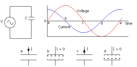
To understand why this is, we should review some of the relevant equations, including:

25_1297704251.gif


relationship between voltage and charge for a capacitor: CV = Q

The AC power supply produces an oscillating voltage. We should follow the circuit through one cycle of the voltage to figure out what happens to the current.

Step 1 - At point a (see diagram) the voltage is zero and the capacitor is uncharged. Initially, the voltage increases quickly. The voltage across the capacitor matches the power supply voltage, so the current is large to build up charge on the capacitor plates. The closer the voltage gets to its peak, the slower it changes, meaning less current has to flow. When the voltage reaches a peak at point b, the capacitor is fully charged and the current is momentarily zero.

Step 2 - After reaching a peak, the voltage starts dropping. The capacitor must discharge now, so the current reverses direction. When the voltage passes through zero at point c, it's changing quite rapidly; to match this voltage the current must be large and negative.

Step 3 - Between points c and d, the voltage is negative. Charge builds up again on the capacitor plates, but the polarity is opposite to what it was in step one. Again the current is negative, and as the voltage reaches its negative peak at point d the current drops to zero.

Step 4 - After point d, the voltage heads toward zero and the capacitor must discharge. When the voltage reaches zero it's gone through a full cycle so it's back to point a again to repeat the cycle.

The larger the capacitance of the capacitor, the more charge has to flow to build up a particular voltage on the plates, and the higher the current will be. The higher the frequency of the voltage, the shorter the time available to change the voltage, so the larger the current has to be. The current, then, increases as the capacitance increases and as the frequency increases.

---------- Post added at 22:55 ---------- Previous post was at 22:54 ----------

A capacitor in an AC circuit exhibits a kind of resistance called capacitive reactance, measured in ohms. This depends on the frequency of the AC voltage, and is given by:

---------- Post added at 22:57 ---------- Previous post was at 22:55 ----------

In simple terms

If the capacitor is connected directly across the AC supply voltage. As the supply voltage increases and decreases, the capacitor charges and discharges with respect to this change.
 
Status
Not open for further replies.

Similar threads

Part and Inventory Search

Welcome to EDABoard.com

Sponsor

Back
Top