Continue to Site

Welcome to EDAboard.com

Welcome to our site! EDAboard.com is an international Electronics Discussion Forum focused on EDA software, circuits, schematics, books, theory, papers, asic, pld, 8051, DSP, Network, RF, Analog Design, PCB, Service Manuals... and a whole lot more! To participate you need to register. Registration is free. Click here to register now.

[PIC] Difference between TRIS = and PORTX.BY =

Status
Not open for further replies.

Eric_O

Advanced Member level 4
Joined
May 31, 2020
Messages
104
Helped
0
Reputation
0
Reaction score
0
Trophy points
16
Activity points
996
Bonjour,

In MikroC, for PIC 16F887 which I’m using now, could some body explain me clearly, simply what the difference between :

TRISD = 0b00001100;
and
PORTD.B2 = 1;
PORTD.B3 = 1;

Before, in main() I wrote ...

PORTD = 0;

Hardware :

switch DOWN connected between GND and pin b2 of PORTD, and pull-up resistor 10 k between VCC and pin b2 of PORTD

switch UP connected between GND and pin b3 of PORTD, and pull-up resistor 10 k between VCC and pin b3 of PORTD

Others questions :

At de beginning of main() is there an order to write ...

PORTD = 0;
TRISD = 0;

or

TRISD = 0;
PORTD = 0;

Can you please remind me which initial and first line of code or necessary in order to set (or reset) properly the MCU ?

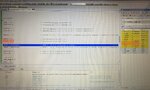
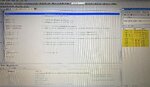
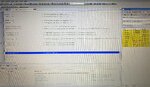
In the attached photo :

The first 5 lines in the beginning on main() are they necessary ? I do not use ADC and Comparators in my code.

PORTD = 0; in the code (left) but PORTD = 00001000 in the Debugger Watch Values window (right).

Merci beaucoup !

Eric
 

Attachments

  • 9A0E34C0-F7D9-4559-BE33-58253B1FEDEC.jpeg
    9A0E34C0-F7D9-4559-BE33-58253B1FEDEC.jpeg
    1 MB · Views: 109

TRISx is the TRI-State control register. It configures the pin to be an input or an output.
PORTx is the data register, it holds the data being sent to the pins if it is in output mode (the TRIS bit is '0') or the data you are reading in from the port if the TRIS bit is '1'.

Yes, you do need to use the first 5 lines of code. If a pin has more than one purpose it will default to one of its input modes (to prevent damage if it is connected to enable something) and if that mode is an analog one it will not read as a digital input.

Brian.
 

    nagkiller

    Points: 2
    Helpful Answer Positive Rating
TRISx is the TRI-State control register. It configures the pin to be an input or an output.
PORTx is the data register, it holds the data being sent to the pins if it is in output mode (the TRIS bit is '0') or the data you are reading in from the port if the TRIS bit is '1'.

Yes, you do need to use the first 5 lines of code. If a pin has more than one purpose it will default to one of its input modes (to prevent damage if it is connected to enable something) and if that mode is an analog one it will not read as a digital input.

Brian.
Cher Brian,
Thanks for this reminder. I still have a problem in my code. In order to debug I deleted all instructions in the do while. I only kept one simple instruction (please see attached photos). Before, in the beginning of main() I kept lines that you recommended me. When using Debbuger and when I run the code line after line, strangely, before running the only one instruction in the do while, In the right Watch Values window, bit 3 of port D is set to 1 ! It’s confusing because in my complete code I have 3 while :

while (portd.b2 == 0 && prod.b3 == 1)
{
....
}


while (portd.b2 == 1 && prod.b3 == 0)
{
....
}


while (portd.b2 == 0 && prod.b3 == 0 )
{
....
}

And when I did run the code with all instructions, the MCU directly runs first while, even if I didn’t push on switches UP and DOWN (see hardware details in my first message).

Do you have an idea of what’s happened ?

Merci beaucoup ! 🙏

Eric
 

Attachments

  • 1B1A3EFF-FF9F-4725-ABFB-F2206213F6D5.jpeg
    1B1A3EFF-FF9F-4725-ABFB-F2206213F6D5.jpeg
    4 MB · Views: 82
  • 94D7B4B5-AB6A-4EAD-825F-AE836F77AAB1.jpeg
    94D7B4B5-AB6A-4EAD-825F-AE836F77AAB1.jpeg
    4.4 MB · Views: 79

Assuming you mean 'portd.b3' instead of 'prod.b3', try changing:
Code:
while (portd.b2 == 0 && portd.b3 == 1)
to
Code:
while ((portd.b2 == 0) && (portd.b3 == 1))
by doing that you ensure that each of the tests for zero are made before it ANDs the results together.

Be careful with that code, it isn't wrong but you should remember that everything between { and } will run all the time the switches are pressed (or not). If you want to to detect a change in the switches you should consider there is a built in 'interrupt on change' circuit that would be more useful.

Brian.
 

    Eric_O

    Points: 2
    Helpful Answer Positive Rating
Not to confuse the situation but code such as
Code:
PORTD.B2=1;
PORTD.B3=1;
can tigger what is known as the 'read-modify-write' (RMW) error. (This is the reason newer chips introduced the LAT register by the way.)
If you need to write to multiple bits in rapid succession, there are a number of techniques you can employ (which I won't go into here - there are plenty of examples in this forum and on the Internet).
I mention this only because it is easy to get into bad habits (without knowing it) with your early programs only to come unstuck later on with more complex code.
Susan
 

Assuming you mean 'portd.b3' instead of 'prod.b3', try changing:
Code:
while (portd.b2 == 0 && portd.b3 == 1)
to
Code:
while ((portd.b2 == 0) && (portd.b3 == 1))
by doing that you ensure that each of the tests for zero are made before it ANDs the results together.

Be careful with that code, it isn't wrong but you should remember that everything between { and } will run all the time the switches are pressed (or not). If you want to to detect a change in the switches you should consider there is a built in 'interrupt on change' circuit that would be more useful.

Brian.
Dear Brian,
Merci beaucoup ! C’est super ! 👍
Clearly it works better !
Eric
--- Updated ---

Not to confuse the situation but code such as
Code:
PORTD.B2=1;
PORTD.B3=1;
can tigger what is known as the 'read-modify-write' (RMW) error. (This is the reason newer chips introduced the LAT register by the way.)
If you need to write to multiple bits in rapid succession, there are a number of techniques you can employ (which I won't go into here - there are plenty of examples in this forum and on the Internet).
I mention this only because it is easy to get into bad habits (without knowing it) with your early programs only to come unstuck later on with more complex code.
Susan
Bonjour Susan,
I miss Australia ! Melbourne, Perth ... beautiful places !
Thanks for your reply. While waiting for the first answer I did search by my own ...
I discovered this interesting link ...
Éric
 
Last edited:

Status
Not open for further replies.

Similar threads

Part and Inventory Search

Welcome to EDABoard.com

Sponsor

Back
Top