Continue to Site

Welcome to EDAboard.com

Welcome to our site! EDAboard.com is an international Electronics Discussion Forum focused on EDA software, circuits, schematics, books, theory, papers, asic, pld, 8051, DSP, Network, RF, Analog Design, PCB, Service Manuals... and a whole lot more! To participate you need to register. Registration is free. Click here to register now.

DHT11 temp/humidity sensor with PIC16f690 in assembly problem

Status
Not open for further replies.

AMukhida

Newbie level 2
Joined
Apr 7, 2012
Messages
2
Helped
1
Reputation
2
Reaction score
1
Trophy points
1,283
Activity points
1,331
Hello all. I just joined the forum and was hoping you all could help me with some problems I've been having. I'm trying to interface a DHT11 with a PIC16f690 and display the results on an LCD. I'm not fully done with the code, but I think I was far enough to display the temperature on the LCD. Anyway, I tested my program out today and I didn't get anything. I'm pretty sure the problem has to do something with the start signal since I tracked RA0 (the pin that is connected to the data line of the DHT11) using an oscilloscope and just got a constant high voltage. The start signal is supposed to make RA0 low for 20ms, then high for 30us, then it gets configured as an input and waits for the response signal from the DHT11. I'm pretty sure I'm looking over something fairly obvious in my code, but I just can't figure it out. If you could help me out with problem, or anything else you see in my code that would be awesome :).
Code:
  processor 16f690
    include <p16f690.inc>

    ;Codeprotect off, watchdog off, internal high speed osc, powerup timer on, clear reset off, brown out off
    __CONFIG _CP_OFF & _WDT_OFF & _INTOSCIO & _PWRTE_ON & _MCLRE_OFF & _BOR_OFF

    CBLOCK      0x20
        BYTE
        Counter
        Integer_RH
        Decimal_RH
        Integer_T
        Decimal_T
        Checksum
        D1
        D2
        Dec_Hun
        Dec_Ten
        Dec_One
        RH_Hun
        RH_Ten
        RH_One
        T_Hun
        T_Ten
        T_One
    ENDC

    #define     LCD_RS  PORTB,5
    #define     LCD_RW  PORTB,6
    #define     LCD_E   PORTB,7
    #define     LED     PORTB,4

    org     0

Main
    ;Initialize Oscillator, 4MHz internal
    BANKSEL     OSCCON                  ;Bank 1
    MOVLW       b'01100000'             ;Set internal oscillator frequency to 4 MHz
    MOVWF       OSCCON
    CLRF        TRISB                   ;port B as output
    CLRF        TRISC                   ;port C as output

    BANKSEL     ANSEL
    CLRF        ANSEL                   ;configure pins as digital
    CLRF        ANSELH
    
Start
    BANKSEL     TRISA
    BCF         TRISA,0                 ;RA0 as output
    BANKSEL     PORTA
    BCF         PORTA,0                 ;RA0 low
    CALL        Delay_20ms              ;RA0 low for 20ms
    BSF         PORTA,0                 ;RA0 high
    CALL        Delay_30us              ;RA0 high for 30us
    BANKSEL     TRISA
    BSF         TRISA,0                 ;RA0 as input
    BANKSEL     PORTA
    CALL        Delay_160us             ;Wait for DHT11 response signal

Read_Integer_RH
    CALL        Read_BYTE
    MOVF        BYTE,W
    MOVWF       Integer_RH              ;Move BYTE to Integer_RH

Read_Decimal_RH
    CALL        Read_BYTE
    MOVF        BYTE,W
    MOVWF       Decimal_RH              ;Move BYTE to Decimal_RH

Read_Integer_T
    CALL        Read_BYTE
    MOVF        BYTE,W
    MOVWF       Integer_T              ;Move BYTE to Integer_T

Read_Decimal_T
    CALL        Read_BYTE
    MOVF        BYTE,W
    MOVWF       Decimal_T              ;Move BYTE to Decimal_T

Read_Checksum
    CALL        Read_BYTE
    MOVF        BYTE,W
    MOVWF       Checksum              ;Move BYTE to Checksum


;CHECKSUM

;CONVERT BINARY VALUES TO ASCII CHARACTERS TO SEND TO LCD
Integer_RH_to_ASCII
    MOVF        Integer_RH,W
    CALL        Convert_to_ASCII
    MOVF        Dec_Hun,W
    MOVWF       RH_Hun
    MOVF        Dec_Ten,W
    MOVWF       RH_Ten
    MOVF        Dec_One,W
    MOVWF       RH_One

Integer_T_to_ASCII
    MOVF        Integer_T,W
    CALL        Convert_to_ASCII
    MOVF        Dec_Hun,W
    MOVWF       T_Hun
    MOVF        Dec_Ten,W
    MOVWF       T_Ten
    MOVF        Dec_One,W
    MOVWF       T_One

;SEND VALUES TO LCD
    ;set interface
     MOVLW        b'00111000'           ;8-bit interface, 2 lines, 5x8 dots
    CALL        SendCommand
    ;enable display, cursor
    MOVLW        b'00001100'            ;display on, cursor off, blinking off
    CALL        SendCommand
    ;clear and home
    MOVLW        b'00000001'
    CALL        SendCommand
    ;set cursor move direction
    MOVLW        b'00000110'
    CALL        SendCommand

    MOVF        T_Hun,W
    CALL        SendCharacter
    MOVF        T_Ten,W
    CALL        SendCharacter
    MOVF        T_One,W
    CALL        SendCharacter

    CALL        Delay_20ms
    GOTO        Start

;********************SUBROUTINES*************************************
Read_BYTE
    CLRF        BYTE                    ;BYTE=00000000
    MOVLW       d'7'                    ;Check_bit 8 times, each time rotating left and updating the LSB
    MOVWF       Counter
    RLF         BYTE,f
    CALL        Check_bit
    DECFSZ      Counter,f
    GOTO        $-3
    RETURN

Check_bit
    CLRF        TMR2
    BTFSS       PORTA,0                 ;Tests until RA0 is pulled high
    GOTO        $-1
    BSF         T2CON,2                 ;Starts TMR2
    BTFSC       PORTA,0                 ;Tests until RA0 is pulled low
    GOTO        $-1
    BCF         T2CON,2                 ;Stops TMR2

    MOVF        TMR2,W                  ;if TMR2>40, bit=1
    SUBLW       d'40'
    BTFSC       STATUS,C                ;if TMR2>40, STATUS,C will be set
    BSF         BYTE,0                  ;sets BYTE,0 to 1 if STATUS,C=1
    BCF         STATUS,C                ;clears STATUS,C
    RETURN

Convert_to_ASCII
    MOVWF       BYTE
    CLRF        Dec_Hun
    CLRF        Dec_Ten
    CLRF        Dec_One
B2D1
    MOVLW       d'100'                  ;move 100 to work
    SUBWF       BYTE,f                  ;BYTE-100
    BTFSS       STATUS,C                ;check if negative value
    goto        B2D2                    ;goto next tens place if value was negative
    INCF        Dec_Hun,f               ;add 1 to hundreds
    GOTO        B2D1                    ;repeat until negative
B2D2
    MOVLW       d'100'
    ADDWF       BYTE,f                  ;add 100 back to make it positive
B2D3
    MOVLW       d'10'                   ;move 10 to work
    SUBWF       BYTE,f                  ;BYTE-10
    BTFSS       STATUS,C                ;check if negative value
    goto        B2D4                    ;goto next tens place if value was negative
    INCF        Dec_Ten,f               ;add 1 to tens
    GOTO        B2D3                    ;repeat until negative
B2D4
    MOVLW       d'10'
    ADDWF       BYTE,W                  ;add 10 back to make it positive and store in work
    MOVWF       Dec_One                 ;remainder is the ones place
    
    MOVLW       h'30'                   ;convert all digits to ASCII
    ADDWF       Dec_Hun,f
    MOVLW       h'30'
    ADDWF       Dec_Ten,f
    MOVLW       h'30'
    ADDWF       Dec_One,f
    RETURN

SendCommand
    BANKSEL     PORTC
    MOVWF       PORTC
    BCF         LCD_RS
    BCF         LCD_RW
    BSF         LCD_E
    CALL        Delay_20ms
    BCF         LCD_E
    return

SendCharacter
    BANKSEL     PORTC
    MOVWF       PORTC
    BSF         LCD_RS
    BCF         LCD_RW
    BSF         LCD_E
    CALL        Delay_20ms
    BCF         LCD_E
    return

Delay_20ms
			;19993 cycles
    MOVLW	0x9E
    MOVWF	D1
    MOVLW	0x10
    MOVWF	D2
L0
    DECFSZ	D1, f
    GOTO	$+2
    DECFSZ	D2, f
    GOTO	L0
			;3 cycles
    GOTO	$+1
    NOP
			;4 cycles (including call)
    RETURN

Delay_30us
    MOVLW	0x09
    MOVWF	D1
L1
    DECFSZ	D1, f
    GOTO	L1
    RETURN

Delay_160us
    MOVLW	0x34
    MOVWF	D1
L2
    DECFSZ	D1, f
    GOTO	L2
    NOP
    RETURN

    END
 

Hello all. I just joined the forum and was hoping you all could help me with some problems I've been having. I'm trying to interface a DHT11 with a PIC16f690 and display the results on an LCD. I'm not fully done with the code, but I think I was far enough to display the temperature on the LCD. Anyway, I tested my program out today and I didn't get anything. I'm pretty sure the problem has to do something with the start signal since I tracked RA0 (the pin that is connected to the data line of the DHT11) using an oscilloscope and just got a constant high voltage. The start signal is supposed to make RA0 low for 20ms, then high for 30us, then it gets configured as an input and waits for the response signal from the DHT11. I'm pretty sure I'm looking over something fairly obvious in my code, but I just can't figure it out. If you could help me out with problem, or anything else you see in my code that would be awesome :).

Hi,

Have not gone though your lenghty code in any detail, have you first tested the lcd routine seperately to prove thats ok ?

Below is the dht11 subroutine I did, it should give you some clearer idea of whats needed.

Its in 18F assembler so there are a few changes you will need to make it 16F compatible, but its not that difficult, MPlab will soon identify the invalid instructions for you, easy enough to replace them.
Its based on a 4mhz osc.

If you are still stuck come on back and include your circuit diagarm as well incase you have any problems there.
 

Attachments

  • dht11.rar
    1.6 KB · Views: 342
Hi,

Have not gone though your lenghty code in any detail, have you first tested the lcd routine seperately to prove thats ok ?

Below is the dht11 subroutine I did, it should give you some clearer idea of whats needed.

Its in 18F assembler so there are a few changes you will need to make it 16F compatible, but its not that difficult, MPlab will soon identify the invalid instructions for you, easy enough to replace them.
Its based on a 4mhz osc.

If you are still stuck come on back and include your circuit diagarm as well incase you have any problems there.

The LCD routine is the same I used for a different assignment, and it worked so I figured it would work in this scenario as well. Could you please post your code.... I don't see it in your post.

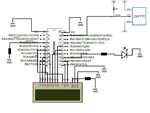
Here is my wiring diagram. Just ignore the LED for now since I will try to implement that later if I have time.
Slide1.jpg
 
Hi,

The code is there in the dht11.rar file, you have to be logged in for it to show up.

I simulated your lcd code and as you say it works fine, though you can use the lcd routine in whats called 4 bit mode and save yourself 4 i/os.
Some helpfull code here - http://www.winpicprog.co.uk/pic_tutorial3.htm


Edit - I can see that code file is there, but perhaps something not quite right at your end so here it is.

Code:
; ***************************************************************************
		
;  DHT11 Routine - requires in main code -
;  #define DHTPORT	PORTA,5     
;  #define  DHTTRIS	TRISA, 5
;  Needs 5k Pullup   : Must be set to Input at power up
;  Must have at least 1 second between reads


DHT11_module
		nop

dhtlp ;	call	delay1sec		  	; 2+ sec delay between reads   - to esure its not read too fast
	;	call	delay1sec

		MOVLW	0x04		   	  	; temp byte counter
		MOVWF	DHTBYCOUNT

        BCF		INTCON, GIE      	; Disable Global Interrupts

		bcf 	DHTTRIS
		bcf		DHTPORT				;	turn off port for 18ms   		-	SEND 18MS START SIGNAL   
		call	delay18ms			; 	SW = 18.02ms 
		bsf		DHTPORT				;  	turm on port 
		nop							;   little pause
		nop
		
		bsf		DHTTRIS				; 	make port input					- RETURN LINE HIGH AND MAKE INPUT
		bcf		DHTPORT
	
		movlw	0x08				; load delay factor 40us			- LOOK FOR DHT LOW RESPONSE WITHIN 40us
		movwf	d1					; SW = 49us
dht40	btfss	DHTPORT				; line should go low within 40us	
		goto	dht80L
		decfsz	d1, f
		goto	dht40
		goto	dhterror			; timeout error
	
	
dht80L	call	delay40us			; delayfor 40us 					- DHT SHOULD GO HIGH AFTER 80us
		movlw	0x08
		movwf	d1					; SW = 49us                          - CHECK FOR LINE HERE
dht40L	btfsc	DHTPORT				; then test line goes high within next 40us  - within total of 80us	
		goto	dht80h
		decfsz	d1, f
		goto	dht40L
		goto	dhterror			; timeout error

dht80h	call	delay40us			; delayfor 40us 					- DHT SHOULD GO LOW AFTER 80us
		movlw	0x08
		movwf	d1					; SW = 49us CHECK FOR LINE HERE
dht40h	btfss	DHTPORT				; then test line goes low within next 40us  - within total of 80us	
		goto	dhtdata				;	- DTH 	FIRST DATA 50us LOW DETECTED - NOW COLECT DATA STREAM
		decfsz	d1, f
		goto	dht40h
		goto	dhterror			; timeout error


dhtdata								;  		- DATA STREAM LOOP
		movlw	0x08				; set up bit counter
		movwf	DHTBITCOUNT


dhtdata_btyeloop
		movlw	0x0A				; load delay factor for 50us
		movwf	d1					; SW = 62us					
									;		- DHT SHOULD GO HIGH AFTER 50us
dht50h	btfsc	DHTPORT				; then test line goes high within next 50us  
		goto	dhtdh
		decfsz	d1, f
		goto	dht50h
		goto	dhterror			; timeout error


dhtdh	movlw	0x06				; load delay factor for 27us		- WHEN DOES DATA HIGH GO LOW ?			
		movwf	d1					; SW = 37us						
															
dhtdhz	btfss	DHTPORT				; then test line goes LOW within next 30us  
		goto	dhtzero				;									- DATA GONE LOW WITHIN 35us SO MUST BE A ZERO
		decfsz	d1, f
		goto	dhtdhz

		movlw	0x07				;  delay another 40us				- DATA IS ONE IF RECEIVED WITHIN 70us
		movwf	d1					; SW = 43us  total high time  37+43= 80us
dhtdh1	btfss	DHTPORT				; then test line goes LOW within next 30us  
		goto	dhtone				;									- DATA GONE LOW WITHIN 35us SO MUST BE A ZERO
		decfsz	d1, f
		goto	dhtdh1
		goto	dhterror			; timeout error

dhtzero	bcf		STATUS,C			; add zero to byte
		goto	dhtaddbit
dhtone	bsf		STATUS,C			; add one to byte
dhtaddbit
		rlcf	DHTBYTE,F
		decfsz	DHTBITCOUNT,F
		goto	dhtdata_btyeloop

							
dhtbyte1 							; first data byte received  - copy to dht_hum
		movlw	0x04
		cpfseq	DHTBYCOUNT
		goto	dhtbyte2
		movff	DHTBYTE, DHTHUM
		decf	DHTBYCOUNT,F
		goto	dhtdata		

							
dhtbyte2 							; second data byte received  - discard - not used
		movlw	0x03
		cpfseq	DHTBYCOUNT
		goto	dhtbyte3
		decf	DHTBYCOUNT,F
		goto	dhtdata		

							
dhtbyte3 							; third data byte received  - copy to dht_temp
		movlw	0x02
		cpfseq	DHTBYCOUNT
		goto	dhtbyte4
		movff	DHTBYTE, DHTTEMP
		decf	DHTBYCOUNT,F
		goto	dhtdata		

							
dhtbyte4 							; fourth data byte received  - discard -not used
		movlw	0x01
		cpfseq	DHTBYCOUNT
		goto	dhtbyte5
;		movff	DHTBYTE, DHTTEMP
		decf	DHTBYCOUNT,F
		goto	dhtdata		


dhtbyte5 							; fifth data byte received  - copy to dht_chksum
		movff	DHTBYTE, DHTCHK
		
        BSF		INTCON, GIE    	    ; Enable Global Interrupts

dhtdisp	movf	DHTHUM,W
		call	ascii
		movff	DIGITLO,t2 		;DHT_HUM_ones
		movff	DIGITHI,t1	    ;DHT_HUM_tens

;	movff	DHTTEMP,BIN
;	call	ascii3
;	movff	ones, E15 				;DHT_TEMP_ones
;	movff	tens, E14   			;DHT_TEMP_tens


;		movff	DHTCHK,BIN
;		call	ascii3

		return


dhterror	
		movlw 	'E'
		movwf	t1
		movlw	'R'
		movwf	t2
        BSF		INTCON, GIE    	    ; Enable Global Interrupts
		return
	

delay40us
		movlw	0x0b
		movwf	d1	
dly40us	decfsz	d1, f
		goto	dly40us
		nop
		return


; Delay = 0.018 seconds
; Clock frequency = 4 MHz

delay18ms
	movlw	0x0F
	movwf	d1
	movlw	0x0F
	movwf	d2
Delay18L
	decfsz	d1, f
	goto dly182
	decfsz	d2, f
dly182	goto	Delay18L

	return
 
Hi eveyone,
I need a help in programming for DHT11 interfacing with PIC16F877A.
I need to transfer my data on Rx, Tx pin of micro controller.
There's a code for on interfacing with LCD but whenever i am modifiying the code for USART my data is not coming on Rx Tx pin.
Please help me with the code.


Code C - [expand]
1
2
3
4
5
6
7
8
9
10
11
12
13
14
15
16
17
18
19
20
21
22
23
24
25
26
27
28
29
30
31
32
33
34
35
36
37
38
39
40
41
42
43
44
45
46
47
48
49
50
51
52
53
54
55
56
57
58
59
60
61
62
63
64
65
66
67
68
69
70
71
72
73
74
75
76
77
78
79
80
81
82
83
84
85
86
87
88
89
90
91
92
93
94
95
96
97
98
99
100
101
102
103
104
105
106
107
108
109
110
111
112
113
114
115
116
117
118
119
120
121
122
123
124
125
126
char message1[] = "Temp = 00.0 C";
char message2[] = "RH = 00.0 %";
unsigned short TOUT = 0, CheckSum, i, Check;
unsigned short T_Byte1, T_Byte2, RH_Byte1, RH_Byte2;
unsigned short Data, DataDir, heck ;
char usart_rd;
 
void StartSignal(){
DataDir = 0;
Data = 0;
Delay_ms(25);
Data = 1;
Delay_us(30);
DataDir = 1;
}
unsigned short CheckResponse(){
TOUT = 0;
TMR2 = 0;
T2CON.TMR2ON = 1;
while(!Data && !TOUT);
if (TOUT) return 0;
else {
TMR2 = 0;
while(Data && !TOUT);
if (TOUT) return 0;
else {
T2CON.TMR2ON = 0;
return 1;
}
}
}
unsigned short ReadByte(){
unsigned short num = 0, t, i;
DataDir = 1;
for(i=0;i<8;i++)
{
while(!Data);
TMR2 = 0;
T2CON.TMR2ON = 1;
while(Data);
T2CON.TMR2ON = 0;
if(TMR2 > 40) num |= 1<<(7-i);
}
return num;
}
 
void interrupt(){
if(PIR1.TMR2IF){
TOUT = 1;
T2CON.TMR2ON = 0;
PIR1.TMR2IF = 0;
}
}
 
void main(){
PORTA = 0b11111111;
PORTB = 0;
TRISB = 0;
PORTC = 0;
TRISC = 0;
PORTD = 0;
TRISD = 0;
CMCON = 7;
INTCON.GIE = 1;
INTCON.PEIE = 1;
 
PIE1.TMR2IE = 1;
T2CON = 0;
PIR1.TMR2IF =0;
TMR2 = 0;
Usart_Init(9600);
Delay_ms(100);
LCD_Init(&PORTD); // Initialize LCD connected to PORTB
 
LCD_Cmd(LCD_CLEAR); // Clear display
LCD_Cmd(LCD_CURSOR_OFF); // Turn cursor off
 
do {
Delay_ms(1000);
StartSignal();
heck = CheckResponse();
if (!check) {
Lcd_Cmd(Lcd_CLEAR);
Lcd_Out(1, 1, "No response");
Lcd_Out(2, 1, "from the sensor");
}
else{
 
RH_Byte1 = ReadByte();
RH_Byte2 = ReadByte();
T_Byte1 = ReadByte();
T_Byte2 = ReadByte();
CheckSum = ReadByte();
 
if (CheckSum == ((RH_Byte1 + RH_Byte2 + T_Byte1 + T_Byte2) & 0xFF))
{
message1[7] = T_Byte1/10 + 48;
message1[8] = T_Byte1%10 + 48;
message1[10] = T_Byte2/10 + 48;
message2[7] = RH_Byte1/10 + 48;
message2[8] = RH_Byte1%10 + 48;
message2[10] = RH_Byte2/10 + 48;
message1[11] = 223;
Lcd_Cmd(Lcd_CLEAR);
Lcd_Out(1, 1, message1);
Lcd_Out(2, 1, message2);
usart_rd = message1;
}
 
else{
Lcd_Cmd(Lcd_CLEAR);
Lcd_Out(1, 1, "Checksum Error!");
Lcd_Out(2, 1, "Trying Again ...");
}
}
 
}while(1);
TRISC = 0;
PORTC = 0;
UART1_Init(9600);
Delay_ms(100);
while(1){
if(UART1_Data_Ready()){
usart_rd = UART1_Read();
UART1_Write(usart_rd);
}

 
Last edited by a moderator:

You are using mikroC PRO PIC. TRISB = 0x20;

The below code is wrong.

Code C - [expand]
1
2
3
4
5
6
7
8
9
TRISC = 0;
PORTC = 0;
UART1_Init(9600);
Delay_ms(100);
while(1){
if(UART1_Data_Ready()){
usart_rd = UART1_Read();
UART1_Write(usart_rd);
}


You should not use UARTx_Init() inside while(1) or do...while(1) loop. UART1_Init() should be before superloop inside the main() function.

UART1_Write() is used to write characters. To send strings use UART1_Write_Text(message1)
 

Attachments

  • DHT11.pdf
    101.9 KB · Views: 165
Last edited:
here is the code:
Code:
/*
 Project: Temperature and humidity measurements using DHT11
 MCU: PIC16F887
 Clock: 10.0MHz external crystal
 Board: UNI-DS6 board
 Date: Jan 10, 2012
 Written by: Rajendra Bhatt (www.embedded-lab.com)
*/


// LCD module connections
sbit LCD_RS at RB2_bit;
sbit LCD_EN at RB3_bit;
sbit LCD_D4 at RB4_bit;
sbit LCD_D5 at RB5_bit;
sbit LCD_D6 at RB6_bit;
sbit LCD_D7 at RB7_bit;

sbit LCD_RS_Direction at TRISB2_bit;
sbit LCD_EN_Direction at TRISB3_bit;
sbit LCD_D4_Direction at TRISB4_bit;
sbit LCD_D5_Direction at TRISB5_bit;
sbit LCD_D6_Direction at TRISB6_bit;
sbit LCD_D7_Direction at TRISB7_bit;
// End LCD module connections


sbit Data at RA0_bit;
sbit DataDir at TRISA0_bit;
char message1[] = "Temp = 00.0 C";
char message2[] = "RH   = 00.0 %";
unsigned short TOUT = 0, CheckSum, i,check;
unsigned short T_Byte1, T_Byte2, RH_Byte1, RH_Byte2;


void StartSignal()
{
  DataDir = 0;
  Data = 0;
  Delay_ms(25);
  Data = 1;
  Delay_us(30);
  DataDir = 1;
}
unsigned short CheckResponse()
{
  TOUT = 0;
  TMR2 = 0;
  T2CON.TMR2ON = 1;
  while(!Data && !TOUT);
  if (TOUT) return 0;
  else
  {
    TMR2 = 0;
    while(Data && !TOUT);
    if (TOUT) return 0;
    else
    {
      T2CON.TMR2ON = 0;
      return 1;
    }
  }
}
unsigned short ReadByte()
{
  unsigned short num = 0, t, i;
  DataDir = 1;
  for(i=0;i<8;i++)
  {
    while(!Data);
    TMR2 = 0;
    T2CON.TMR2ON = 1;
    while(Data);
    T2CON.TMR2ON = 0;
    if(TMR2 > 40) num |= 1<<(7-i);
  }
  return num;
}

void interrupt()
{
  if(PIR1.TMR2IF)
  {
    TOUT = 1;
    T2CON.TMR2ON = 0;
    PIR1.TMR2IF = 0;
  }
}

void main()
{
  PORTA = 0b11111111;
  PORTB = 0;
  TRISB = 0;
  PORTC = 0;
  TRISC = 0;
  PORTD = 0;
  TRISD = 0;
  CMCON = 7;
  INTCON.GIE = 1;
  INTCON.PEIE = 1;

  PIE1.TMR2IE = 1;
  T2CON = 0;
  PIR1.TMR2IF =0;
  TMR2 = 0;

  Delay_ms(100);
  Lcd_Init();
  Lcd_Cmd(_Lcd_Clear);
  Lcd_Cmd(_LCD_CURSOR_OFF);
 while(1)
  {
    Delay_ms(1000);
    StartSignal();
    check = CheckResponse();
    if (!check) 
    {
      Lcd_Cmd(_Lcd_Clear);
      Lcd_Out(1, 1, "No response");
      Lcd_Out(2, 1, "from the sensor");
    }
    else
    {
      RH_Byte1 = ReadByte();
      RH_Byte2 = ReadByte();
      T_Byte1 = ReadByte();
      T_Byte2 = ReadByte();
      CheckSum = ReadByte();

    if (CheckSum == ((RH_Byte1 + RH_Byte2 + T_Byte1 + T_Byte2) & 0xFF))
    {
      message1[7] = T_Byte1/10 + 48;
      message1[8] = T_Byte1%10 + 48;
      message1[10] = T_Byte2/10 + 48;
      message2[7] = RH_Byte1/10 + 48;
      message2[8] = RH_Byte1%10 + 48;
      message2[10] = RH_Byte2/10 + 48;
      message1[11] = 223;
      Lcd_Cmd(_Lcd_Clear);
      Lcd_Out(1, 1, message1);
      Lcd_Out(2, 1, message2);
    }
    else
    {
      Lcd_Cmd(_Lcd_Clear);
      Lcd_Out(1, 1, "Checksum Error!");
      Lcd_Out(2, 1, "Trying Again ...");
    }
   }
  }
}


I'm using PIC16F877A with 8MHz external X-Tal. And DHT11 sensor.

Hope for a solution soon.

- - - Updated - - -

The circuit is showing "No response from the sensor"!
 

Yeah!, Its working. But not getting the decimal value. I mean its just showing 31.0,32.0,33.0 etc not 31.4,32.6 ect.

Can you tell me how can I get that data?
 

Yes, for both temp. & hum. not getting any value after '.' .

- - - Updated - - -

can you tell me where is the error? Also I tried to convert the data C to F with this equation:
Code:
 value =   (T_Byte1*100)+T_Byte2;
         
         value = (value*1.80)+32.00; // Celcious To Farenhite convershion
         
         ch = (value / 1000) % 10;
         Lcd_Chr(1,8,48+ch);
         ch = (value / 100) % 10;
         Lcd_Chr_Cp(48+ch);
         Lcd_Chr_CP('.');
         ch = (value/ 10)% 10;
         Lcd_Chr_CP(48+ch);
         Lcd_Chr_Cp(223);
         Lcd_Chr_CP('F');

Here also having some error. Because its not showing the exact F value.
 

See if this works.

Code C - [expand]
1
2
3
4
5
6
7
8
9
10
float value;
unsigned char fltval[23];
 
 
value =   (T_Byte1*100.0)+T_Byte2;
         
value = (value*1.80)+32.00; // Celcious To Farenhite conversion
 
FloatToStr(value, fltval);
LCD_Out(1,1,fltval);


I will check the datasheet of DHT11 and reply. I have to see the format of data it sends.

Try this

value = (float) (T_Byte1*100.0)+T_Byte2;


Edit:

Revert back to the original code which worked yesterday after adding ADCON1 settings and then use the below code.

Code C - [expand]
1
2
3
4
5
6
7
message1[7] = T_Byte1/10 + 48;
      message1[8] = T_Byte1%10 + 48;
      message1[10] = T_Byte2 + 48;
      message2[7] = RH_Byte1/10 + 48;
      message2[8] = RH_Byte1%10 + 48;
      message2[10] = RH_Byte2 + 48;
      message1[11] = 223;


Measure the temperature with DHT11 and also another reference digital thermometer. See if both gives the same reading.


Code C - [expand]
1
2
3
4
5
6
7
8
9
10
11
12
13
14
15
16
17
18
19
message1[7] = T_Byte1/10 + 48;
message1[8] = T_Byte1%10 + 48;
 
if(T_Byte2 > 0) && (T_Byte2 < 10)
    message1[10] = T_Byte2 + 48;
else if((T_Byte2 > 9) && (T_Byte2 < 100)){
    message1[10] = T_Byte2/10 + 48;
    message1[11] = T_Byte2%10 + 48;
}       
else if((T_Byte2 > 99) && (T_Byte2 < 256)){
    message1[10] = T_Byte2/100 + 48;
    message1[11] = (T_Byte2/10)%10 + 48;
    message1[12] = T_Byte2%10 + 48;
}         
 
message2[7] = RH_Byte1/10 + 48;
message2[8] = RH_Byte1%10 + 48;
message2[10] = RH_Byte2 + 48;
message1[11] = 223;

 
Last edited:

I tested it. It shows the value. Maybe the T_Byte2 is always 0 and so 0 is displayed. Maybe DTH11 is sending 0 for the 2nd byte of Tempearture and RH.


Post the code that you used to test.
 

Status
Not open for further replies.

Part and Inventory Search

Welcome to EDABoard.com

Sponsor

Back
Top