Striplar
Newbie level 4
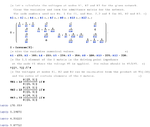
Don't be fooled, this problem at first appears trivial, and then impossible.
Before you ask, there is no way to take out any of the resistors from the mesh or to know their values by their markings. The project is commercially sensitive so I'm afraid the discussion is going to have to be restricted to the example given. In the real world problem, the mesh will be very much larger but the resistor values will all be within +/-20% of each other. I've exaggerated the values in the example to make it easier to conceptualise where the currents are flowing.
The problem is simply this. If we know the voltages at all of the nodes, and we know the voltage across the mesh and, crucially, the current flowing from the voltage source, how can the resistor values be calculated?
I've shown the resistor values that were used to calculate the node voltages so that I know the correct solution to the problem. You have to imagine that you don't know any of the resistor values, these at what I'm trying to deduce.
Here are a few thoughts....
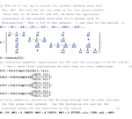
Node or mesh analysis can't provide enough equations for the number of unknown resistors.
If you were to allow the values of the bridging resistors to become infinite, multiple solutions are possible, but this won't be the case in practice.
My guess is that you can't solve this using classical methods because those methods can't accommodate those infinite values and discount them.
Once you add the constraint that no resistor can have an infinite value, I think there is only one solution, but I have no idea how to find it.
Any ideas?
**broken link removed**
Before you ask, there is no way to take out any of the resistors from the mesh or to know their values by their markings. The project is commercially sensitive so I'm afraid the discussion is going to have to be restricted to the example given. In the real world problem, the mesh will be very much larger but the resistor values will all be within +/-20% of each other. I've exaggerated the values in the example to make it easier to conceptualise where the currents are flowing.
The problem is simply this. If we know the voltages at all of the nodes, and we know the voltage across the mesh and, crucially, the current flowing from the voltage source, how can the resistor values be calculated?
I've shown the resistor values that were used to calculate the node voltages so that I know the correct solution to the problem. You have to imagine that you don't know any of the resistor values, these at what I'm trying to deduce.
Here are a few thoughts....
Node or mesh analysis can't provide enough equations for the number of unknown resistors.
If you were to allow the values of the bridging resistors to become infinite, multiple solutions are possible, but this won't be the case in practice.
My guess is that you can't solve this using classical methods because those methods can't accommodate those infinite values and discount them.
Once you add the constraint that no resistor can have an infinite value, I think there is only one solution, but I have no idea how to find it.
Any ideas?
**broken link removed**
Last edited: