Continue to Site

Welcome to EDAboard.com

Welcome to our site! EDAboard.com is an international Electronics Discussion Forum focused on EDA software, circuits, schematics, books, theory, papers, asic, pld, 8051, DSP, Network, RF, Analog Design, PCB, Service Manuals... and a whole lot more! To participate you need to register. Registration is free. Click here to register now.

[SOLVED] Designing circuit for providing isolation

Status
Not open for further replies.

ans94

Newbie level 5
Joined
Jun 5, 2015
Messages
9
Helped
0
Reputation
0
Reaction score
0
Trophy points
1
Activity points
76
I have to measure voltage across capacitor which acts as a dc source in a cascaded h-bridge inverter and input it to the dsp (digital signal processor). I have designed a voltage measurement circuit which senses the pulsating dc voltage across the capacitor and steps it down to 3.3V (since the max voltage input to the dsp is 3.3V ) using a voltage divider circuit and a differential opamp. Now before giving the 3.3V output to the dsp, I need to isolate it. What is the possible method to do so? Can i use an optocoupler? I have gone through few optocouplers but am not sure which one to use and how to use it.
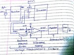
 

This is the circuit. New Doc 6_1.jpg
 

You don't need an opto isolator, the differential amplifier will give you complete isolation.

Just the standard four resistor diffential amplifier circuit:
https://upload.wikimedia.org/wikipe.../1280px-Op-Amp_Differential_Amplifier.svg.png

Make R1 and R2 both 200K
Rg and Rf should be 2K4

That will give you 3.0 volts out for 250 volts in, allowing for a bit of measurement headroom if the 250 volts goes a bit high.
 
  • Like
Reactions: ans94

    ans94

    Points: 2
    Helpful Answer Positive Rating
A differential amplifier with symmetrical voltage divider would be also my standard solution. It should be mentioned that it involves a leakage current according to the common voltage between high voltage and measurement circuit.

The circuit must be designed to tolerate the leakage current, e.g. with respective grounding, the amplifier should also provide a margin for additional common mode voltage and suppress high frequency common mode interfernces.
 

Assuming the HV is the rectified mains and the uP is on an isolated o/p, then you do need to isolate the signal, you can use a freq to voltage converter and put the freq across a small Tx or opto, with a freq to voltage converter on the uP side...
 

I assumed he was rectifying the square wave output from an inverter.
Its the only way you can get 250v dc from 250v ac.

But it could (?) be mains,and that changes quite a few things if it is.
 
  • Like
Reactions: ans94

    ans94

    Points: 2
    Helpful Answer Positive Rating
Status
Not open for further replies.

Similar threads

Part and Inventory Search

Welcome to EDABoard.com

Sponsor

Back
Top