Continue to Site

Welcome to EDAboard.com

Welcome to our site! EDAboard.com is an international Electronics Discussion Forum focused on EDA software, circuits, schematics, books, theory, papers, asic, pld, 8051, DSP, Network, RF, Analog Design, PCB, Service Manuals... and a whole lot more! To participate you need to register. Registration is free. Click here to register now.

Designing a sine wave inverter using push pull transformer with center tape

Status
Not open for further replies.

naseerak

Full Member level 5
Joined
Jun 14, 2003
Messages
241
Helped
19
Reputation
38
Reaction score
19
Trophy points
1,298
Activity points
1,222
Hi
I have done many designs on H-bridge from opt-couplers and discrete logic to dedicated H-Bridge drivers. But Now I want to design a sine wave inverter using push pull transformer with center tape. actually one of my design based on atmega8 has a square wave out put now I want to change the software making an spwm signals driving the same center taped transformer with addition of filter cap on the output if the transformer. I want your suggestions before getting in to it currently I am using 12-0-12 to 280 v transformer.
Regards
 

Re: H-Bridge Vs Pushpull

Hi naseerak
How much is your required current and how about frequency of your sine wave ? 280 volts RMS ? ( it's peak will be 280*sqrt(2) ) .
Best Wishes
Goldsmith
 

Re: H-Bridge Vs Pushpull

It depends on load power and your ability in software to control dead time on H bridge to avoid demise of crosstalk shunting the rails with current feedback for timing and voltage feedback for levels.

I would suggest a hardware solution.

Look at this reference design.
http://www.irf.com/technical-info/refdesigns/irsolwib.pdf

Q1 is sine pulse width modulated (sine PWM) while Q4 is kept on.

Screen shot 2012-07-24 at 5.43.48 PM.png
 

Re: H-Bridge Vs Pushpull

Thanks for the quick reps but i need clarification regarding H-Bridge and push pull my Intended wattage is around 1400 watts. I just want to know should the center tap be used for this purpose. my spwm frequency is around 15khz.
my trafo has already the specs which is often used for square wave inverters. No problem as I can rewind the trafo for any specs. the main question is if H-bridge is suggested why it would be preferred over the center tap.
 

Re: H-Bridge Vs Pushpull

The H-bridge allows higher power rating (for the same transformer primary) since it allows you to use more turns of the primary at the same current level. This means higher "effective" input voltage. The drawback of H-Bridge is the higher cost of 4 switches + drivers while the push-pull only needs 2 low side switches which are easier to drive.
 

Re: H-Bridge Vs Pushpull

At power levels of >1000W, usually H-bridge is recommended. One definite advantage is you don't have flux walking due to asymmetrical design.
 

Re: H-Bridge Vs Pushpull

At power levels of >1000W, usually H-bridge is recommended.
Agreed. And even regardless of topology, drawing 1.4KW from 12VDC is going to require some very heavy cabling, if possible you should try and work from >24VDC.
One definite advantage is you don't have flux walking due to asymmetrical design.
Technically all double-ended topologies, including the full bridge, can suffer from flux walking, though usually this is easily dealt with by using current mode control.
 

Re: H-Bridge Vs Pushpull

Hi Agreed to all of you but the main point here is that the existing mod-square wave inverters can be converted to sine wave by changing only the software.
Does the above rules applies to the square wave inverters too or in the case of sine wave only. batteries cascading is another story and i Know the rules of this business.
 

naseerak

most definitely you have to change the software. you will have to create a sine look up table for the micro. then you will walk through the table using timers at a frequency you wish to generate.

all thanks to thamids tutorial on generating sinewave with micro

you can check out is blog then u will learn more.

then about hardware.
since you are using a iron core transformer that means you have to switch at the rate of 50/60hz or your core will saturate and heat up.
if your transformer is outputting 24 volts (end to end) when u supply 280vac then that means you will need a voltage of about 36 - 38vdc to get the 280vac when you are inverting. that is if you are using a full bridge config.

you will have to worry about designing an LC lowpass filter to remove the high frequency of your carrier signals generated by your micro.

hope this helps
 

Hi
BTW what should be the maximum spwm frequency for big iron core trafo as the market is flooded with these type inverters driving large iron core trafos with relatively high frequencies.
 

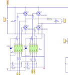
Using IRL1803 MOSFETS rated at 30V 6mΩ 150A an H bridge step up may be possible for your XFMR without centre tap.

You need to count every mΩ in the primary switching path and keep the return path close to source.

Screen shot 2012-08-01 at 12.24.01 AM.pngScreen shot 2012-08-01 at 12.23.00 AM.png

PWM and commutation for A/B must be well controlled from code.
A safety overload should be added.
Use ferrite beads and CM choke where needed to drive XFMR.

U+ is your 12V source with low ESR < 5mΩ polyester caps.
<A/B> commutation mux and <PWM> sine mux from your PIC ports.
<A> & <B> are your output to primary side of XMFR.

Primary wiring needs to be in the same <5mΩ range. !!
consider bi-filar windings or tri-filar and double insulated tape.

100uF polyester cap https://www.digikey.com/product-detail/en/FFV34E0107K--/478-2614-ND/717556is < 1mΩ ESR but 100mΩ reactance @16KHz and $33/pc so you might want to rethink your low switching rate.
 
Last edited:

Status
Not open for further replies.

Similar threads

Part and Inventory Search

Welcome to EDABoard.com

Sponsor

Back
Top