Continue to Site

Welcome to EDAboard.com

Welcome to our site! EDAboard.com is an international Electronics Discussion Forum focused on EDA software, circuits, schematics, books, theory, papers, asic, pld, 8051, DSP, Network, RF, Analog Design, PCB, Service Manuals... and a whole lot more! To participate you need to register. Registration is free. Click here to register now.

designing a lowpass filter for audio

Status
Not open for further replies.

shoe

Newbie level 6
Joined
Apr 5, 2010
Messages
11
Helped
0
Reputation
0
Reaction score
0
Trophy points
1,281
Location
edinburgh
Activity points
1,397
Hello All, I am a musician and I am branching out into electronics.
I'm a fairly technically minded person, I took tech at school and got an A+ but
that was years ago and I think i've forgotten everything, so i'd appreciate a
bit of help designing a variable frequency lowpass filter suitable for audio. One day my dream is to build a full analog synthesizer.

i.e 1 - 250000 Hz, 16 bit or better resolution, sampling frequency > 44Khz and with (this is the tricky bit:) a variable frequency lowpass cutoff from 1 - 25,000 Hz ( I know, audible range is 1hz - 20khz but if you have a trained ear, you can definately hear the higher frequencies. Many audiophiles beleive that the 1 - 20 level which is banded about is really just a crude approximation.)

So, here is something I designed in filterlab. Its a four stage butterworth, Im not sure if it is fit for purpose and it definately isn't variable, its simply 1000hz fixed.

I would like to make this smoothly sweepable, from 0 hz upwards, so that I can filter my sounds through it.

I have only a vauge idea of how to implement this though; so Im looking for some guidance from any audio fiends out there.

Thankyou everyone, for your help.
 

A 1:10 frequency range can be achieved with variable resistors, possibly up to 1:30 or even 1:100 with logarithmic characteristc.
But you need one variable resistor for each filter order, would be 8 for your filter. I don't actually see the purpose of an 8th order filter
for usual audio applications, but also for standard 3rd or 4th order crossover-filters, you often need to design your own multi-potentiometer
mechanics. A filter circuit, that uses equal R values should be preferred, but it's feasible for butterworth.

Larger frequency range filters would better use electronical variable filters (as known e.g. from a Moog synthesizer). They have more
noise and distortion than a fixed or variable resistor filter, however. State-of-the-art professional equipment is more and more using digital
signal processing for filters, by the way.
 

FvM said:
A 1:10 frequency range can be achieved with variable resistors, possibly up to 1:30 or even 1:100 with logarithmic characteristc.
But you need one variable resistor for each filter order, would be 8 for your filter. I don't actually see the purpose of an 8th order filter
for usual audio applications, but also for standard 3rd or 4th order crossover-filters, you often need to design your own multi-potentiometer
mechanics. A filter circuit, that uses equal R values should be preferred, but it's feasible for butterworth.

Larger frequency range filters would better use electronical variable filters (as known e.g. from a Moog synthesizer). They have more
noise and distortion than a fixed or variable resistor filter, however. State-of-the-art professional equipment is more and more using digital
signal processing for filters, by the way.

Yeah, I know. Everyone is all about DSP.

So, I need to build a multi-potentiometer, electronically controlled which splits over all of those orders of filter?
 

I haven't checked the data sheet yet but the humble MF10 filter comes to mind. You can control it's cut-off frequency by changing it's clock. Works in low-pass, high-pass and bandpass modes if my memory serves me well.

It's probably not the lowest noise solution but assuming your application is producing sound anyway, any background mush should be drowned out by your music.

Brian.
 

shoe said:
................
So, I need to build a multi-potentiometer, electronically controlled which splits over all of those orders of filter?

Are you aware of the fact that tuning the pole frequency is not possible without changing the pole Q of each filter stage - thereby loosing the Butterworth response ?
 

any background mush should be drowned out by your music
The original post mentioned 16 bit resolution, MF10 or other switched capacitor designs are clearly much worse, also many voltage
controlled tunable filters have difficulties to achieve CD audio quality.

A method, that was quite popular in 70ths audio effects is using LDR as variable resistors. The response time isn't very fast, but usually
sufficient with 1:1000 resistance ratio.
 

LvW said:
shoe said:
................
So, I need to build a multi-potentiometer, electronically controlled which splits over all of those orders of filter?

Are you aware of the fact that tuning the pole frequency is not possible without changing the pole Q of each filter stage - thereby loosing the Butterworth response ?

No, I wasn't! Im a complete newbie who'd just like to learn more about filters, and build his own (then i'll probably use it a couple times and record the output)
So, tell me which kind of filter I should be making?

betwixt said:
assuming your application is producing sound anyway, any background mush should be drowned out by your music.

Im sorry but your logic is completely screwed! How did anyone ever lay down a clean recording with that atttitude? this filter must have a relatively high signal to noise ratio! very low hiss and no hum!!! (what's the point in doing it if you're not going to do it properly?

To all: i've actually just realised that a butterworth, having a flat response is not actually very interesting musically: so, could anyone suggest other filter designs which I could build?
For example, the roland tb-303 uses a 12db lpf which has a curious resonance quirk, allowing it to produce those squelchy sounds. i'd love to build a replica, but i've read that its hard to find the components and im not sure enough to design a mock up using different components. I don't know though, total newbie.

Ideas?? :)
 

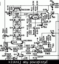
tb-303 utilizes a voltage controlled 4th order filter with a variable feedback. It has surely more than 12 db/octave roll-off.


As you can see from the circuit detail, the filter is based on diodes as variable differential resistances. It's a simple basic circuit,
but it's dynamic properties are of course not corresponding to the requested CD audio quality.
 

Years ago I used the LMF40 and LMF60 switched capacitor Butterworth lowpass filter ICs with built-in oscillator for audio circuits. They were excellent.

I guess I was the only guy to buy them because they soon became obsolete.
Today, Maxim make similar ICs.
 

LMF100 as a MF10 replacement is still in production at National.
 

I used the LMF100 as the notch filter in my distortion analyser. It uses the same clock as my very low distortion sine-wave generator so they match.
 

Is that what everyone does, just buys IC's with the filters allready prefabricated?

I was hoping somone could, for interests sake, help me turn a vacuum tube into a filter. I'd need to know the differences between a op-amp's response, input, voltages, etc and a vacuum tube's though. I think its do-able since they have the same function...
 

I don't know why you want to reduce high audio frequencies to make a muffled sound.
I also don't know why you want the cutoff frequency to be adjustable.

An opamp has a voltage gain of up to 1 million.
A vacuum tube has a voltage gain of only about 100 if it is half a 12AX7.

An opamp has distortion as low as 0.00008%.
A vacuum tube has distortion as high as 10%.

An opamp lasts forever.
A vacuum tube wears out soon.
 

shoe said:
Is that what everyone does, just buys IC's with the filters allready prefabricated?
I was hoping somone could, for interests sake, help me turn a vacuum tube into a filter. I'd need to know the differences between a op-amp's response, input, voltages, etc and a vacuum tube's though. I think its do-able since they have the same function...

When you clearly describe your problem resp. your request I am sure somebody from the forum would give you some help.
However, I really don`t know what you are asking for. In your first posting it was a 4-stage Butterworth filter with tunable bandwidth; now you tell us something about the differences between opamps and vacuum tubes ...
My recommendation is, you should try to formulate clear understandable questions.
Regards.
 

@Audioguru (good name btw...)
Audioguru said:
I don't know why you want to reduce high audio frequencies to make a muffled sound.
I also don't know why you want the cutoff frequency to be adjustable.

Im not sure what kind of music you listen to, but filters of this kind have been used since the 50's and 60's. The reason is because it sounds good. Filters are extensively used in modern electronic music, and frequently in other genres too. The filter, in its own right, could be termed a musical instrument.

Example MP3 attached (trance, psychedelic) :D

An opamp has distortion as low as 0.00008%.
A vacuum tube has distortion as high as 10%.

Yes, but this is not necessarily a bad thing. Vacuum tubes produce analog clipping (which has a soft, rounded character to the waveform) vs. digital distortion (which has a very harsh, square character to the waveform)

although obviously both kinds of distortion are modeled with modern DSP effects, and used extensively, analouge distortion is generally preferable. I wasn't able to find a waveform output of the difference, sorry; but in a nutshell a transistor will clip the signal to a dead stop, whereas an op amp will allow the signal to carry on a little, has a little tollerance. I think mathematically there is an exponential in the analog amplification process, tending toward infinity whereas with digital it produces gain up to the maximum and then no more. If I am wrong about this, tell me as im only 99% sure.
 

FvM said:
tb-303 utilizes a voltage controlled 4th order filter with a variable feedback. It has surely more than 12 db/octave roll-off.

You're right sorry its 18db. Its quite non-standard as far as filters go, their usually either 12db or 24db.
 

It's no problem, if you can't specify the intended filter properties in terms of filter order or characteristic, it's O.K. if you try to describe the
intended usage and subjective effect. Some points have been partly misleading, however. Referring to a fixed frequency butterwort and
mentioning "frequency sweeping ability" doesn't particularly a voltage controlled filter, as you later asked for. The vacuum tube idea is more a
counterpoint to IC filters rather than a good design idea, I think. Of course, you can build active filters with vacuum tubes, but they don't offer
any advantage in making it sweepable.
 

shoe said:
Im not sure what kind of music you listen to, but filters of this kind have been used since the 50's and 60's. The reason is because it sounds good. Filters are extensively used in modern electronic music, and frequently in other genres too. The filter, in its own right, could be termed a musical instrument.

Example MP3 attached (trance, psychedelic) :D
I heard your variable muffling effect and I have heard it before. A switched capacitor lowpass filter IC will do it very simply.

... (clipping's severe distortion) ...
Overdrive is a form of severe distortion. There are many ways to make the signal clipped.
 

Hi shoe,

but in a nutshell a transistor will clip the signal to a dead stop, whereas an op amp will allow the signal to carry on a little, has a little tollerance. I think mathematically there is an exponential in the analog amplification process, tending toward infinity...

Please, if you could explain these statements somewhat ("carry on a little"..."little tolerance"... "exponential in the amplification"). Sounds a bit uncommon.
 

A transistor and an opamp (made with transistors) clip the signal to a dead stop because they convert the signal to a square-wave when they clip.

A vacuum tube clips gradually so the signal "carries on a little higher" when it begins to clip so the clipping does not sound as harsh as solid state and allows a higher output swing.
 

Status
Not open for further replies.

Similar threads

Part and Inventory Search

Welcome to EDABoard.com

Sponsor

Back
Top