Continue to Site

Welcome to EDAboard.com

Welcome to our site! EDAboard.com is an international Electronics Discussion Forum focused on EDA software, circuits, schematics, books, theory, papers, asic, pld, 8051, DSP, Network, RF, Analog Design, PCB, Service Manuals... and a whole lot more! To participate you need to register. Registration is free. Click here to register now.

Designing a ac/dc smps

Status
Not open for further replies.

pc9460

Junior Member level 3
Joined
Jul 16, 2015
Messages
27
Helped
0
Reputation
0
Reaction score
0
Trophy points
1
Activity points
214
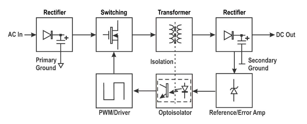
I have to design an ac/dc smps for one of the requirements for my capstone project. It will have an input of 120V AC wall outlet and an output of 5V DC at 1A. I have found many different types of smps designs online and don't know which one to use. I can design the bridge rectifier and size the transformer easily. I can't buy any ic's like a buck converter off digikey and have to make a custom smps as apart of my agreement. The easier the design the better as I've only taken two electronics courses and went over basic power supplies briefly. Can anyone point me in the right direction? A very basic block diagram would help.
 

Have a look at this: https://www.homemade-circuits.com/2014/03/12v-5-amp-transformerless-battery.html

This one seems to be more simple than any IC based SMPS.
You can remove the emi filter and thermistor if you wish. Replace 13.5v zener with a 5.1 or 5.6v zener and check the output. If you don't have 6A4 diodes, replace them with two parallel 1N4007 diodes. 4N35 can be replaced with PC817 or any similar optocoupler. You can do some little bit modification of your own.
 

Is there a very basic block digram available for a smps?

Would this block diagram that I drew up be considered a smps? Anything that I'm missing? I'm just trying to build a basic smps to power some basic circuitry like leds, pic chip, etc.. Block.JPG
 

Here is a basic schematic.


Notice a transformer is not essential.

It could be an advantage to reduce mains voltage with a transformer. That will give you isolation from high voltage, as well as make it a little easier to adjust the duty cycle.
 

Block.JPG

Would this block diagram that I drew up work?
 

Would this block diagram that I drew up work?

Yes, the first three blocks go into an everyday DC power supply. Popular and easy to make. But that part is not the smps, of course. The last block is the smps, and it is not as simple as one block would lead you to think.

To make up a buck converter you only need a few components, in the theoretical sense. Then you'll also need to add control circuitry, and components as such an on-off indicator, circuit protection, etc.
 

I tried making the buck converter in that pdf I attached in the post above and couldn't get it to simulate. Would should I be using to do the PWM on multisim? I've spent hours on it and can't get it right, the output still ends up to be ~12VDC. I understand all the calculations but can't make it work on multisim!

- - - Updated - - -

I found this on the NI Forums and run it myself but get approximately 11.3VDC, this is the same exact circuit that I posted the pdf for. Can anyone help?
https://forums.ni.com/ni/attachments/ni/370/16779/1/buck converter Ideal.ms13
 
Last edited:

Take a look at my smps simulations in the thread below. They were created in Falstad's animated interactive simulator. (Your computer needs to have Java installed.)

The link will:
a) Open the site www.falstad.com/circuit
b) Load my schematic into the simulator
c) Run it on your computer

https://www.edaboard.com/threads/268178/

Click your mouse on the switch to start the first half of the cycle. Release to go to the second half. Observe action through the inductor. Observe how the action affects the output voltage.

Before long you'll get a tempo going. Adjust output voltage by changing the tempo.

You can change values at will. Right-click a component, select Edit.
 

I think the only problem I'm having now is the pwm input for the mosfet. Can anyone help me out? I've posted my multisim file above, I can't get the right output voltage...
 

PWM for buck converter

I am trying to design a buck converter but cant get the pwm to work so my mosfet will act like a switch. I have a 12V dc input and trying to bump it down to 5v dc. Can anyone help me figure out how to get the buck converter to work?!?! I've spent countless hours on it.. I've attached what I have so far.

Buck.JPG
 

Status
Not open for further replies.

Similar threads

Part and Inventory Search

Welcome to EDABoard.com

Sponsor

Back
Top