Welcome to our site! EDAboard.com is an international Electronics Discussion Forum focused on EDA software, circuits, schematics, books, theory, papers, asic, pld, 8051, DSP, Network, RF, Analog Design, PCB, Service Manuals... and a whole lot more! To participate you need to register. Registration is free. Click here to register now.
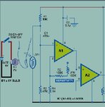
I have seen a circuit diagram used for heart beat monitoring system using Ldr and lm358n.Can any one tell me about the design of resistor and capacitors used there.?My objective is to count the number of pulses coming from the outpin pin (7) of lm358n.
The resistors need to have an ohm value that is in approximately the same range with the photocell resistance.
If their value was small, it would involve large current flows, making it impossible to detect changes in the small currents flowing through the photocell.
The capacitor C2 is commonly advised for the purpose of reducing noise on the supply line (either incoming noise or noise caused by the device itself).
The second op amp is set for maximum gain (because there is no feedback to the inverting input).
If a small signal (or large signal) comes from the first op amp, the second op amp will amplify it further so that its amplitude is the same as the supply voltage.
This site uses cookies to help personalise content, tailor your experience and to keep you logged in if you register.
By continuing to use this site, you are consenting to our use of cookies.