Continue to Site

Welcome to EDAboard.com

Welcome to our site! EDAboard.com is an international Electronics Discussion Forum focused on EDA software, circuits, schematics, books, theory, papers, asic, pld, 8051, DSP, Network, RF, Analog Design, PCB, Service Manuals... and a whole lot more! To participate you need to register. Registration is free. Click here to register now.

Design of non-inverting schmitt trigger circuit

Status
Not open for further replies.

Pradeepbp

Junior Member level 2
Joined
Sep 21, 2013
Messages
23
Helped
9
Reputation
18
Reaction score
9
Trophy points
3
Location
Kerala
Visit site
Activity points
214
Hi,
I want to design a non-inverting schmitt trigger circuit with VTL= -8V, VTH=0V and VOH=5V, VOL=0V.
checked in net, the formula given is VTH = R1/R2 * Vsat. But I need VTH to be zero. And im quite confused with the design concept here.
Can somebody pour some light? :) Please explain your approach.
 

what if R2>>>R1 example : R2=100k , R1=100ohm or 1k . the Vth will be very small , which comparable to zero does this work with your needs??

another way is to use a comparator with an opamp that operate with 0 and 5v supply like : LM368
 
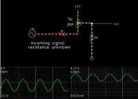
This simple trick with a potentiometer can be used to add a few volts to your incoming signal, while attenuating it, so that it occupies the positive polarity.


Or, you can use an op amp in summing configuration to achieve the same thing, although you need to provide it with a bipolar supply.

Your schmitt trigger stage is next.

Or with some ingenuity it might be possible to do all jobs with a single op amp.
 
Hi, Thanks for your reply.
Previous stage of opamp is a summer circuit. So i can shift voltages. Now I have configured my summer circuit to output voltage between 0 to 10V.
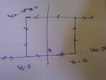
I need a non-inverting schmitt trigger circuit with Vl=(0 or 1V) and Vh = (10 or 9V). (I can provide 1 V tradeoff for noise and attenuation).

My problem is designing the schmitt trigger circuit.
VOH/ +Vsat can be 15V or 10V or 5V. VOL/-Vsat has to be 0V. Schmitt ckt drives a switching circuit of next stage.
I checked 741, if i ground -Ve power terminal, then i can get a voltage swing of +Vsat to 13V and -Vsat to 0V.
Now how to design the circuit?

Here is the graph what i need: DSC_0026.jpg

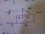
Im trying to design with this figure..
DSC_0027.jpg

But not getting. Should i give any Vref?
Do explain your result. Or send any link where i can study 'design for any given Vl and Vh.
Thanks :)
 

- Connect a voltage divider (R3/R4) from supply to the inverting OP input to provide an adjustable reference voltage
- Derive expressions for low and high threshold voltages
- Calculate R1/R2 and R3/R4 ratio to meet your specifications

Rather visually, R1/R2 ratio sets the hysteresis (difference between both threshold voltages) and R3/R4 jointly shifts both thresholds
 
Status
Not open for further replies.

Similar threads

Part and Inventory Search

Welcome to EDABoard.com

Sponsor

Back
Top