Continue to Site

Welcome to EDAboard.com

Welcome to our site! EDAboard.com is an international Electronics Discussion Forum focused on EDA software, circuits, schematics, books, theory, papers, asic, pld, 8051, DSP, Network, RF, Analog Design, PCB, Service Manuals... and a whole lot more! To participate you need to register. Registration is free. Click here to register now.

Design of Interleaved Boost Converter

Status
Not open for further replies.

ssheikmd

Member level 1
Joined
Feb 9, 2009
Messages
37
Helped
1
Reputation
2
Reaction score
1
Trophy points
1,288
Activity points
1,521
Dear All,

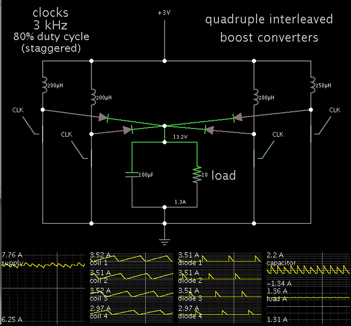
I have been reading interleaved boost converter related paper for couple of months now. I understand the concept of the converter. But, I couldn't find any useful formulas to design L&C values. Again, some claims the formulas are same as that of boost converter.. Here I need two things (a) Formulas to find L& C values. (b) If formulas are same as that of boost converter then in a two phase converter the inductor value should be as what we calculate or else should apply the parallel inductor equation..

Regards,

Sheik
 

There are many ap notes on designing boost converters. If you are going to interleave them you would design each section to be a fraction of the load depending on how many sections you will interleave.

If you design a 36vdc 10A boost converter and interleave 2 of them you will get 36vdc at 20A. If you use 3 of them you will get 36vdc at 30A.

The hard part of interleaving boost converters is the controller for them. I searched for them once and i think i only found a controller for interleaving 2 boost converters.

The reason it is so difficult for the controller is that each section must monitor current and all sections must cooperate and divide the current equally.
 

Using Falstad's simulator, I have experimented with numerous interleaved converters.

Here is a screenshot of quadruple interleaved boost converters.


Notice I made the last coil higher than the others by 25%. I made the clocks evenly spaced.
The results of the simulation show current flow through the oddball is 16% less than the others (not 25% as we would expect).
 

Status
Not open for further replies.

Similar threads

Part and Inventory Search

Welcome to EDABoard.com

Sponsor

Back
Top