Continue to Site

Welcome to EDAboard.com

Welcome to our site! EDAboard.com is an international Electronics Discussion Forum focused on EDA software, circuits, schematics, books, theory, papers, asic, pld, 8051, DSP, Network, RF, Analog Design, PCB, Service Manuals... and a whole lot more! To participate you need to register. Registration is free. Click here to register now.

[SOLVED] Design of a PIC12F683 based temperature controlled DC fan

Status
Not open for further replies.

omega6

Member level 3
Joined
Oct 14, 2008
Messages
55
Helped
8
Reputation
16
Reaction score
8
Trophy points
1,288
Location
Sri Lanka
Activity points
1,652
Hi Guys,

I'm attempting to build a temperature controlled DC fan based on a PIC12F683 micro controller. Currently my circuit is not working and i need some help to find out the problem. So far this is what i have.

Code:
  unsigned long int Temp;
  unsigned int adc_sample_1, adc_sample_2;
  unsigned int adc_sample_3, adc_sample;
  int scale_coeff = 2932;

  void main() {

  WDTCON = 0x0018;   //Enable Watchdog timer
  PWM1_Init(19530); //Initialize PWM at 19.53KHz (per pic spec-sheet allows 10bit resolution)
  ADC_Init();       //Initialize ADC
  ADCON0 = 0x1F;    //Set VDD as Vref, ANO as analog read
  TRISIO.B2 = 0;    //Set pin 5 (CCP1) as output, used for PWM
  TRISIO.B0 = 1;     //Set pin 7  (ANO) as input, used for ADC read


  while(1){

  //ADC Read at ANO
  adc_sample_1 = ADC_Read(0);
  Delay_ms(1000);

  adc_sample_2 = ADC_Read(0);
  Delay_ms(1000);

  adc_sample_3 = ADC_Read(0);
  Delay_ms(1000);

  adc_sample = (adc_sample_1 + adc_sample_2 + adc_sample_3)/3; //Take 3 sample from ADC and take the average


  //Read ADC Channel 1
  Temp = (adc_sample*scale_coeff)/10000; //Using Integer calculation

  //PWM formular for 10 bit resolution: (Percent*1023)/100

  if(Temp > 30 && Temp < 40)
  {
     PWM1_Set_Duty(307);   //Set PWM to 30%
       PWM1_Start();
    }

  else if(Temp > 40 && Temp < 50)
  {
      PWM1_Set_Duty(512);  //Set PWM to 50%
       PWM1_Start();
    }

  else if(Temp <= 30)
  {
     PWM1_Set_Duty(0);   //Trun off PWM
        PWM1_Stop();

        break;     //Breaks program  out of the while loop and causes it to re-initialize all the registers/start over the process.
   }

  }

  }


This is the schematic

PIC12F683 Temperature controlled Fan.png

Appreciate any help and suggestions provided in this matter.

Thank You.
 

You didn't say which compiler you are using.

I suspect a math error is your problem. If possible trace the values in your ADC measurements, you might need to place an '(unsigned int)' cast before your ADC measurements. Try to avoid anything but the simplest integer math, there is no need to multiply by 2932/10000 for example, just adapt the limits in your value tests to the native average of the ADC readings. Also be careful of the braces in the checks, for example should:
if(Temp > 30 && Temp < 40)
really be:
Code:
if((Temp > 30) && (Temp < 40))
?

Brian.
 
Code:
TRISIO.B2 = 0;    
TRISIO.B0 = 1;     
ADC_Read(0);
PWM1_Set_Duty(307);
PWM1_Start();
PWM1_Stop();
PWM1_Init(19530); //Initialize PWM at 19.53KHz (per pic spec-sheet allows 10bit resolution)
  ADC_Init();

This will not work as PWM_Set_Duty() argument should be in the range of 0 to 255 (8 bit). I don't know why compiler didn't give error when you used 512.
Code:
PWM1_Set_Duty(512);
 
  • Like
Reactions: omega6

    omega6

    Points: 2
    Helpful Answer Positive Rating
Without knowing which compiler was used you can't say whether it's limit is 255 or not. With 10-bit resolution the value should be in the range 0 to 1024. We don't know if these PWM routines are standard library functions or ones specially written for the program.

Brian.
 

Hi Brian

Those functions are mikroC PRO PIC Compiler library functions. If you open the mikroC PRO PIC Compiler's help and search for PWM1 and ADC then you will get details on how to use those functions. I have checked them and PWM1_Set_Duty() will only take values from 0 to 255.
 

Hi Brian,

I'm using the mikroC PRO PIC Compiler as pic.programmer stated. I'm really new to pic programming and wasn't sure how to do thing the proper way.

- - - Updated - - -

Hi pic.programmer,

You are correct. I should divide 1023 by 4 to get the proper value. The compiler didn't show any errors at the time of compiling the above mentioned code.
 

Hi Guys,

I'm still trying to get my PIC12F683 based temperature controlled DC fan to work, but with no luck. No matter how much i try the fan won't spin at all. I do not have any special equipment to debug this or even see the temperature reading. This is the new code i have. I'm using mikroc as the ide.

Code:
  const unsigned short VREF = 5.00;
  float Temp_C;
  unsigned int adc_sample;

  void main() {

  WDTCON = 0x0018;   //Enable Watchdog timer
  ADC_Init();       //Initialize ADC
  ADCON0 = 0x1F;    //Set VDD as Vref, ANO as analog read
  TRISIO.B2 = 0;    //Set pin 5 (CCP1) as output, used for PWM
  TRISIO.B0 = 1;     //Set pin 7  (ANO) as input, used for ADC read

  PWM1_Init(5000); //Initialize PWM at 19.53KHz (per pic spec-sheet allows 10bit resolution)
  PWM1_Start();

  while(1){

  //Read ADC Channel 1  
  adc_sample = ADC_Get_Sample(0);


  //Temp_C = (adc_sample * VREF)/10.240;  // Calculate temperature in Celsuis
  Temp_C = (adc_sample * VREF)/49.960;


  //PWM formular for 8 bit resolution: (Percent*255)/100

  if((Temp_C >= 30) && (Temp_C <= 40))
  {

     PWM1_Set_Duty(127);  //Set PWM to 50%

    }

  else if((Temp_C >= 41) && (Temp_C <= 50))
  {

      PWM1_Set_Duty(191);   //Set PWM to 75%

    }

  else if(Temp_C > 50)
  {
     PWM1_Set_Duty(255);   //Set PWM to 100%

   }

  else if(Temp_C < 30)
  {
     PWM1_Set_Duty(0);   //Trun off PWM
  //      PWM1_Stop();

   }


  Delay_ms(500);
  }

  }

I'd appreciate if anyone can kindly check this code and point out the errors as a help.


Thank You.
 

Check the WDTCON settings, they are currently using a 'reserved' value with the WDT turned off in software. It can be overridden by the CONFIG word which you have not specified but must be set somewhere else. If you really do want the WDT running, make sure you clear it inside the program loop or the PIC will keep resetting itself.

I'm still not sure why you do all the math, I would start by using the ADC value directly until you are sure the rest of your code/hardware is working. For example:
Code:
  //Read ADC Channel 1  
  adc_sample = ADC_Get_Sample(0);

  if((adc_sample >= 100) && (adc_sample <= 120))    // using these numbers as examples
  {

     PWM1_Set_Duty(127);  //Set PWM to 50%

    }

Check the math anyway, using you present calculation, an ADC result of 1 gives Temp_C = (adc_sample * VREF)/49.960; = (1 + 5)/49.96 = 0.12 degrees
and if the ADC reads full scale (1023+5)/49.96 = 20.576 degrees so the PWM will always be turned off. To work out the relationship between temperature and ADC measurement you need to know how many volts per degree your sensor produces.

Brian.
 

Hi Brian,

I have already enabled the WDT in the code. I do not understand what you mean by "they are currently using a 'reserved' value with the WDT turned off in software". Could you please tell me how to override by the CONFIG word.

Is my math wrong or too much for this program. I think according to the formula it should be (1 * 5)/49.96 = 0.10 degrees. Am i correct.


Thank You.
 

Code:
  WDTCON = 0x0018;   //Enable Watchdog timer
From the Microchip data sheet:
bit 7-5 Unimplemented: Read as ‘0’
bit 4-1 WDTPS<3:0>: Watchdog Timer Period Select bits
Bit Value = Prescale Rate
0000 = 1:32
0001 = 1:64
0010 = 1:128
0011 = 1:256
0100 = 1:512 (Reset value)
0101 = 1:1024
0110 = 1:2048
0111 = 1:4096
1000 = 1:8192
1001 = 1:16384
1010 = 1:32768
1011 = 1:65536
1100 = Reserved
1101 = Reserved
1110 = Reserved
1111 = Reserved
bit 0 SWDTEN: Software Enable or Disable the Watchdog Timer(1)
1 = WDT is turned on
0 = WDT is turned off (Reset value)
Note 1: If WDTE Configuration bit = 1, then WDT is always enabled, irrespective of this control bit. If WDTE
Configuration bit = 0, then it is possible to turn WDT on/off with this control bit.

For the temperature to ADC reading conversion you need to know how many Volts per degree output you get from your sensor. The LM35 gives 10mV per degree and a single step in the ADC is Vref/1024. If you use VDD as the reference, each measurment step is 4.88mV or approximately 2 steps per degree. That means that without dropping Vref or amplifying the sensor voltage, you will never be able to measure more accurately than about 0.5C.

Brian.
 

The base current is defined by:

  • (VCC-Vbe)/R1 = 4,3/470 ~0,91mA
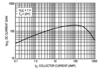
But you must be aware that there are 2 variants of the transistor BC337 that you are using: One having a typical DC gain of 250 and another with 400, and assuming the worst case, according to its charactreristic gain curve:
gain.PNG
This would produce a DC gain of ~80, so Ic=80*0,91mA=73mA.
I'm sure this do not suffice to turn any fan.

In addition, I also did´t see any capacitor at the base of the transistor.
Add one having the value of somewhat few above to C~1/(R1*FPWM_period)
 

Yes the choice of power switch is flawed. Use a <200mV switch Ron= 0.2V/Ifan

Unless a PWM fan is chosen .ok, otherwise the PWM may cause aliasing with commutation with weird effects in a 2 wire fan.

Full on to off range should be ~10'C to prevent hunting.
This requires some spreadsheet calculations.
 

Hi andre_teprom,

The fan actually turn on. It's a 12V @ 350ma fan. I think the problem is with the code. According to mikroc forum the ADC_Get_Sample output a decimal value between 0 to 1023.

When i measured the room temperature with a arduino it shows between 27c to 29c. My laptop temperature is around 40c to 45c. When i place the lm35 near the laptop exhaust the fan does not turn on. According to the arduino it is 41c. To my surprise if i change the condition to (adc_sample >= 20) the fan turn on. How is this possible. Why is the arduino reading the correct temperature and the PIC not.

All suggestion and help is really appreciated.

- - - Updated - - -

Hi andre_teprom,

Could you please explain the need for a capacitor at the base of the transistor. This circuit is not originally mine but was found elsewhere.

All suggestion and help is really appreciated.
 

Zip and post the mikroC project files. I will check the code and fix the problem.
 

Hi pic.programmer,

Right now I'm unable to send the files. As soon as i get home I'll upload the project files to you.


Thank You.

- - - Updated - - -

Hi Brian,

For now I have disabled the WDT and using below code to find the exact problem.

Code:
  unsigned int Temp, Temp_Old;
  unsigned int adc_sample;

  void main() {

  //WDTCON = 0x0018;   //Enable Watchdog timer
  ADC_Init();       //Initialize ADC
  ADCON0 = 0x1F;    //Set VDD as Vref, ANO as analog read
  TRISIO.B2 = 0;    //Set pin 5 (CCP1) as output, used for PWM
  TRISIO.B0 = 1;     //Set pin 7  (ANO) as input, used for ADC read

  PWM1_Init(5000); //Initialize PWM at 19.53KHz (per pic spec-sheet allows 10bit resolution)
  PWM1_Start();

  while(1){

  adc_sample = ADC_Read(0);

  //Read ADC Channel 1
  Temp = (adc_sample/4); //Convert 10 bit ADC value to 8 bit value


  if(Temp != Temp_Old)
  {

  //PWM formular for 8 bit resolution: (Percent*255)/100

  //if(Temp >= 30)
  if(Temp >= 20)
  {
     PWM1_Set_Duty(255);   //Set PWM to 100%

   }

  //else if(Temp < 30)
  else if(Temp < 20)
  {
     PWM1_Set_Duty(0);   //Turn off PWM
 

   }

  Temp_Old = Temp;

  }

  Delay_ms(500);
  }

  }


If i change the condition to (adc_sample >= 20) the fan turn on and all is good. I don't understand why the temperature is below the expected value.

All suggestion and help is really appreciated.
 

This code

Code:
adc_sample = ADC_Read(0);

should be replaced by

Code:
adc_sample = (unsigned long)ADC_Read(0) * 500 / 1024;

adc_sample should be unsigned long type.

If LM35 gives 1.5V then it is 150 deg C. So, for 5V it should be 500 deg C.

Code:
unsigned int Temp, Temp_Old;
 unsigned long adc_sample;
 unsigned int raw_adc_value = 0;

  void main() {

  //WDTCON = 0x0018;   //Enable Watchdog timer
  ADCON0 = 0x1F;    //Set VDD as Vref, ANO as analog read
  TRISIO.B2 = 0;    //Set pin 5 (CCP1) as output, used for PWM
  TRISIO.B0 = 1;     //Set pin 7  (ANO) as input, used for ADC read

  PWM1_Init(5000); //Initialize PWM at 19.53KHz (per pic spec-sheet allows 10bit resolution)
  PWM1_Start();

  while(1){

  raw_adc_value = ADC_Read(0);	
  adc_sample = (unsigned long)raw_adc_value * 500 / 1024;

  //Read ADC Channel 1
  Temp = (raw_adc_value/4); //Convert 10 bit ADC value to 8 bit value


  if(Temp != Temp_Old)
  {

  //PWM formular for 8 bit resolution: (Percent*255)/100

  if(Temp >= 30)
  {
     PWM1_Set_Duty(255);   //Set PWM to 100%

   }

  else if(Temp < 30)
  {
     PWM1_Set_Duty(0);   //Turn off PWM
 

   }

  Temp_Old = Temp;

  }

  Delay_ms(500);
  }

  }
 
Last edited:
  • Like
Reactions: omega6

    omega6

    Points: 2
    Helpful Answer Positive Rating
Could you please explain the need for a capacitor at the base of the transistor. This circuit is not originally mine but was found elsewhere.

This tend to reduce voltage spikes at transistor collector which could stress it. Although for this case in particular whose polarization is not fully saturated, the damping effect due to this capacitance could reduce it ability to startup from inertia.
 

If LM35 gives 1.5V then it is 150 deg C. So, for 5V it should be 500 deg C.
According to the LM35 data sheet (https://www.ti.com/lit/ds/symlink/lm35.pdf, Table 6.3), Tmin is -55C and Tmax is 150C.
The output voltage is linearly proportional to the temperature (at 10mV/C) but that does not mean it is as simple as 10mV = 1C. For example, if that were the case, then what is the output voltage for -30C (for example) with respect to GND.
Susan
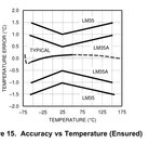
LM35 really is that simple, except for -ve temps you need the appropriate package and a negative bias R on the output.
Error tolerances are given. Supply recommended is 4V~30V


50'C = 500mV
Design target error is 0.5'C accuracy from room temp.
Worst case specs are in datasheet.
lm15.jpg

The driver design is still weak and dependent on product variations, which would translate into poor yields in production.
 

Hi pic.programmer,

I tried your code and still it's not working. I have attached the project files as requested. It has all the possible things i have tried. Could you please have a look at it and try it from your end to see if its working.

All suggestion and help is really appreciated.

Thank You.
 

Attachments

  • Temperature controlled DC fan 2.rar
    26.7 KB · Views: 152
  • Like
Reactions: PLEG54

    PLEG54

    Points: 2
    Helpful Answer Positive Rating
Status
Not open for further replies.

Similar threads

Part and Inventory Search

Welcome to EDABoard.com

Sponsor

Back
Top