Continue to Site

Welcome to EDAboard.com

Welcome to our site! EDAboard.com is an international Electronics Discussion Forum focused on EDA software, circuits, schematics, books, theory, papers, asic, pld, 8051, DSP, Network, RF, Analog Design, PCB, Service Manuals... and a whole lot more! To participate you need to register. Registration is free. Click here to register now.

Design equations for microstrip antenna..

Status
Not open for further replies.

karthiprime

Member level 2
Joined
Mar 19, 2012
Messages
42
Helped
1
Reputation
2
Reaction score
1
Trophy points
1,288
Activity points
1,526
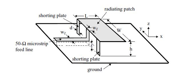
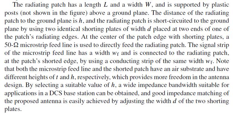
I have been involved in the design of the Broadband microstrip antenna.

In the way, i have planned to Use Shorted microstrip patch antenna, for which i couldnt find the design equations.

Can anyone tell me where i could find the design equations. (I got only design equations for basic design equations for microstrip antenna from balanis book).

thank u..
 

Hello,

You may try "Compact & Broadband Microstrip Antennas", by K. Wong. Regarding "design equations"; If you want to design something new, innovative, you may need to do everything yourself.

Note that small, high gain and wide band don't go together.
 
Hi..

I referred tat book.. It dont have any design equations it.. It has just the results of the designs..

and reference IEEE papers too dont have design equations.

wondering how to design without design equations!!
 

Design is done with equations, but you have to harvest your equations from various sources and basic understanding of EM theory.

If you want to design a new antenna geometry (so not using a recipe), you mostly approximate the structure with lumped circuit and/or transmission line models to get some idea of current distribution, voltage distribution, impedance, etc. You add some length or capacitance to correct for fringing (there are empirical formulas for fringe correction). You may use image theory to assess the effect of a ground plane.

The current distribution you need to guess (or calculate) the radiation pattern.

Simulation is used to adjust the size of the geometry to get exactly what you want. When you understand what you are doing, you need a limited number of iteration to get what you want.
 
Didnt think i got this much work (starting with the deriving design equations)..

Thanks..
 

What geometry do you (or your colleges) have in mind to get wide band behavior, w.r.t. a standard half wave resonating patch antenna?

You may know that a half wave resonating patch above ground plane (height/lambda < 0.1 lambda) has small BW/fc by nature. You may also know that when height/lambda is small, BW/fc will be small also.

To make it broadband, you need to change the geometry, or add additional things to allow (for example) other resonances. One can think of parasitic patches, slots, non-radiating (LC) resonators, etc.

Designing antennas with multiple resonances to increase BW is really difficult, as changing the geometry changes the center frequency of the individual resonances and the coupling between them. Formulas with wide applicability are not available as far as I know.
 
Am designing basestation antenna (GSM ~ 890 - 915 : 25 MHz bandwidth).

As of now, i finished the simulation of single patch, half wave resonating antenna. Got just 3 MHz impedence bandwidth at -10 dB return loss..

Gone through various techniques to increase B.W ( especially compact and broadband antennas book) and chosen the Microstrip line fed shorted patch geometry ( among techniques like aperture coupled, proximity coupled, adding chip resistor, stacked shorted patch, bowtie etc ), where height and width of the shorting plates affects the characteristics. I chosen this geometry to proceed with, as it looks simple than others ( correct me if it not so).

I have an idea of the how radiation occurs in simple patch antenna and how its equation derived ( w.r.to Antennas by balanis).

Now got stuck with the design of the Microstrip line fed shorted patch geometry, as it requires the design equations ( I think even with other geometry no design equations available)..

NOTE : I never thought to proceed with dual frequency antennas/ multiple patches, as it may increase the complexity for a beginner..
We can find the details of the Microstrip line fed shorted patch geometry from 'compact and broadband antennas' book, Page no :50..
 

Can you post your geometry (for those that don't have the book)?

Increasing the height above groundplane increases bandwidth as there is less canceling of radiation due to the negative image in the ground given certain current in the patch. Don't add resistors as this reduces gain, but it may result in a better match. In fact you move the loss from the PA final mosfet towards the resistor in the antenna.

Having air under the patch (instead of dielectric material) increases the size of the patch, hence increasing bandwidth.

I made a guess on the current distribution of your shorted patch. The E-field plane is XZ plane (similar to that of a PIFA). You can see significant radiation under low elevation in the XZ plane.This is due the the shorting plates vertical current.

In the H-field plot (YZ plane), there is less radiation under low elevation. I can't explain this. There is separation between the shorting plates in Y direction, but it is well below 0.5 lambda to get significant attenuation of the vertical polarized component in the YZ plane. So I expected more radiation under low elevation for the cross pol. component.

If you would scale this design to 900 MHz, you should have 90 MHz BW (VSWR=1.5), as they state BW=10% in the reference.
 
Last edited:
This is the geometry.. and description


---------- Post added at 21:32 ---------- Previous post was at 21:14 ----------

Can we calculate Bandwidth mathematically??
 

Status
Not open for further replies.

Part and Inventory Search

Welcome to EDABoard.com

Sponsor

Back
Top