Continue to Site

Welcome to EDAboard.com

Welcome to our site! EDAboard.com is an international Electronics Discussion Forum focused on EDA software, circuits, schematics, books, theory, papers, asic, pld, 8051, DSP, Network, RF, Analog Design, PCB, Service Manuals... and a whole lot more! To participate you need to register. Registration is free. Click here to register now.

Design and model of a dc/dc buck converter

Status
Not open for further replies.

prawesh2000

Junior Member level 1
Joined
Apr 23, 2012
Messages
17
Helped
1
Reputation
2
Reaction score
1
Trophy points
1,283
Location
Ronneby, Sweden
Activity points
1,407
Hello, everyone!

I want to build a dc-dc converter using a microcontroller TIF28027. The specificatons are:

Input voltage: 9 V
Output voltage: 3-4 V
I load: 5 A
Switching frequency: 330 KHz
Ripple current: 10%
Ripple voltage: 5%

But I am pretty confused on where to start...What are the components that will be used? I need to make a model in Simulink and the PCB layout in DipTrace.
Can anyone provide me with step-by-step guide, please!
 

Dear Prabesh
Hi
It is simple . try to use an opto coupler or an ICL7667 to increase the out put of your microcontroller up to 15 volts , and then use a boot strap driver e.g IR2110 or IR2130 or IR2113 or .... etc . and then famous arrangement of buck converter .
Best Wishes
Goldsmith
 

I am sorry I didn't get you goldsmith...we are required to use inductors, capacitors, switches and micro-controller only. we should use 2 switches and the timing of the switches is controlled in the micro-controller. the micro-controller should be programmed in matlab.

I am still at the initial stage of selecting the components and their values...For the details, we need to do the following:

a) Components and their values selection
b) Modeling and simulation of the dc-dc converter circuit
c) Design a PCB layout (later the teacher will order it when its approved)
d) Program the micro-controller in MATLAB
e) Testing
f) Presentation and final report

I am at scratch because I skipped some lectures...May be you can help me in this step-by-step procedure...
 

Hi again
Are you familiar with theorem of buck converter ? if no , how you want design it ? do you need just formulas ?
and another thing : do you like to build it in matlab just ? not in practice ?
Best Wishes
Goldsmith
 

Yes, I am familiar with the its working theory...I have been reading papers but nothing enters my head. I have to model and simulate it in simulink, program the microcontroller in Matlab and then design the converter in real-life for my project. I still stand at the same position as when I started 2 weeks ago. I have a deadline for the submission on 25th of May.

If you can help me with this project, I would be much thankful to you my friend. Please guide me through the whole process. If its okay, may we can chat over some IM or facebook?
 

Dear Prabesh
Hi
Sorry because of my long delaying .
Unfortunately , i can't help you with mathlab , but , about design in real life , i can help you . Where is your problem ?
And about face book , unfortunately , i didn't enter , on it , until now , because of some reasons , e.g my time ! i'm a bit busy , and some of my time is with EDA board , and some of that ........... .
Best Wishes
Goldsmith
 

Yeah the given are:
Input voltage: 9 v
Output voltage: 3-4 v
Load current: 5 A
Ripple current: 10%
Ripple voltage: 5%
Switching frequency: 330 KHz

I have to design the converter using 2 switches, a capacitor and an inductor. How can I find the values of all the components?
 

Hi again
It is very simple .
For out put inductor of a buck converter we will have this formula : L=((5*(Vs-Vo))/Ion)*Vo*t/Vs
That Vs is input voltage and vo is out put voltage . Ion is nominal current ( maximum out put current ) . and t is time (1/fsw)
for capacitor there are many ways , that you can try , such as a way that based on ESR value and some approximations . but here is a simpler way that i have used for many times , successfully . C=I/F*vrpp ( it is a famous formula , that you can use here ) . and for two switch : you'll need a bootstrap driver such as IR21xx , ( IR2113 /IR2110/IR2130 ..... etc )
But here will be a problem if you just use a one switch : your bootstrap capacitor can't find any loop , to the ground ! so it can't be full of charge ! and your H side can't be turn on . and you'll need another switch ! . you don't need any independent diode as a famous diode that we will use for each buck converter . you can use an n- mosfet as a diode ! it will has an antiparallel diode that will do the duty of that famous diode at your buck converter . but when you give it a PWM' ( and PWM to the H side ) that capacitor can be full of charge with this path .
BTW : don't forget to create enough dead time .
Best Wishes
Goldsmith
 
Hello!
Thanks goldsmith; I appreciate your help! Although, I have come up with some more questions, hope you will answer them too.

1. What is the 'vrpp'? Is it the voltage ripple?
2. I have not been told about the bootstrap driver by my professor. But, yes, he told that we are going to use a gate driver. Are they same?
3. I have to use two switches. So, I have to find the Ton and Toff for both of the switches. How can I do that?
4. How can I find the total power loss in the circuit? They said that the converter should give >85% efficiency.

This much for now. Awaiting for your reply.
 
Dear Prabesh
Hi
1. What is the 'vrpp'? Is it the voltage ripple?
Yes , it means peak to peak ripple voltage .
2. I have not been told about the bootstrap driver by my professor. But, yes, he told that we are going to use a gate driver. Are they same?
It is simple ! both are the same ! if you use two mosfet ( h side , and l side ) that both of them are nmosfet , for lside you won't have any problem but for h side mosfet , you'll have problem ! you can connect the ground of control signal ( PWM ) to the minus supply but you can't connect it to the source of h side mosfet . so we have to use a method that called bootstrap ( it isn't the way that you probably hear at class A amplifier ! , it is completely different ) . so , here in this project you haven't minus supply , but if you want to drive your hside mosfet , that bootstrap capacitor , can't be full of charge , because it hasn't any loop , to the ground ! so , if you use another mosfet instead of diode at buck regulator , usually , they have a diode , internally , that called anti parallel diode . this diode will do duty of that famous diode at buck configuration , and this mosfet will provide a path to the ground , thus , your bootstrap capacitor can be full of charge . this capacitor will connect to the GS junction of your mosfet automatically , and thus your mosfet can be turn on / turn off , easily .
Did you understand ? ( if no , no problem , i can make a diagram for you to achieve better understanding .)
3. I have to use two switches. So, I have to find the Ton and Toff for both of the switches. How can I do that?
It isn't important to find ton and toff ! do you know why ? because if you have PWM for your series switch , the command signal of another mosfet will be PWM' . but not , pwm' , exactly . you'll need to create enough dead time , with a simple shmitt trigger not gate and an RCD network to prevent overlap problem .

4. How can I find the total power loss in the circuit? They said that the converter should give >85% efficiency.
For efficiency , calculations , of a simple buck converter , we can use a simple approximation ( according to the pressman's book ) that loss power , is equal to the value of current ! so we can say efficiency = pout/(pout+ploss+prect)
if we neglect from p rect ( rectifier dissipation ) we can say : ploss = pout/pout+ploss .
Let me show you an example :
we have a buck regulator , which has 10 A at the out put , and vout= 50 v and vin =60v . loss power =10 (approx)
Thus efficiency = 500/500+10 which approximately is 98 percent . however , for more precision you can solve this equation :
Dissipation power across your mosfet = 1/T integral over ( Rdson*ID^2) dt from zero up to ton .
If you can see any obscure thing , in my discussions , tell , me , please , that i simplify it .
Best Wishes
And Good luck for your project
Goldsmith
 
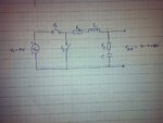
photo.JPG

This is the model of the converter I am supposed to design and make. When I presented the L and C values using the formulas you gave me, he asked me the question "How and where did you find this formula? Where is the derivation? How can you prove that this formula is legit? What is the '5' in the formula for the value of L?" and stuffs. And I got stuck as I didn't know the answers.
Now, only fews weeks are remaining to complete the project I don't have a clue of what I am doing and what I am supposed to do.
Could you please be kind and explain me everything on what's going on, a definite formula for the L and C, the exact ESR values for both the L and C, values for Ton and Toff, RDson and RDsoff for the switches, what switches and values should I use, the efficiency of the converter and many other questions that I could not remember but you think are important and useful?

I am not being a parasite but I really need to finish this project in time to gain my credits.
 

Hi again .
Humm ! don't worry , today , i'll attach some pages of pressman's book , that you can see , that where those formulas are from ! ( it is easy )
Best Events
Goldsmith

---------- Post added at 19:06 ---------- Previous post was at 19:05 ----------

By the way , what is your mean by RL , that is in series with inductor ? is that ohmic resistor of inductor ?
 

Yeah, RL is the resistance of the inductor and Rc is the resistance of the capacitor.

Thank you in advance for the references you are going to attach. If possible, please show me the way to find out everything I mentioned earlier like ESR, Ton, Toff and stuffs.
 

Hi again
As i asked from moderators of this forum , attaching that pages can be considered as an infraction . so , if it is possible , give me , your email , i can send you some references .
Best Wishes
Goldsmith
 
Status
Not open for further replies.

Similar threads

Part and Inventory Search

Welcome to EDABoard.com

Sponsor

Back
Top