Continue to Site

Welcome to EDAboard.com

Welcome to our site! EDAboard.com is an international Electronics Discussion Forum focused on EDA software, circuits, schematics, books, theory, papers, asic, pld, 8051, DSP, Network, RF, Analog Design, PCB, Service Manuals... and a whole lot more! To participate you need to register. Registration is free. Click here to register now.

Describe in VHDL a generator parallel 4 bits to serial 1 bit

Status
Not open for further replies.

isamel85

Newbie level 6
Joined
Nov 6, 2011
Messages
11
Helped
0
Reputation
0
Reaction score
0
Trophy points
1,281
Activity points
1,416
Hello,
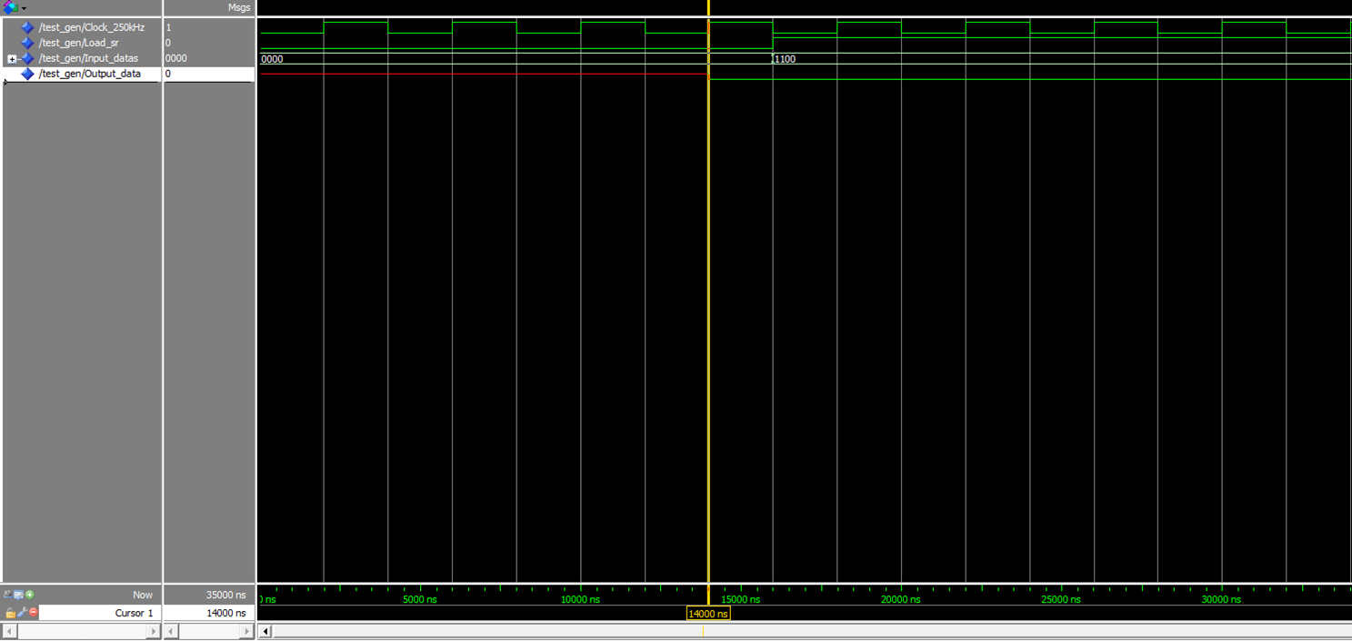
I want to describe in VHDL a generator parallel 4 bits to serial 1 bit.
Indeed, at each clock edge (250 kHz), we take only one bit starting with the least significant bit (LSB).
Example:
Input = "0101" (over 4 bits)
So at first clock edge, output = '1' (LSB)
Second clock edge, output = '0'
Third clock edge, output = '1'
Fourth clock edge, output = '0' (MSB)
There's someone there who can help me?
And thank you
 

Ignoring all the declarations and the other verbose stuff...

Code VHDL - [expand]
1
2
3
4
5
6
7
8
9
10
11
process (clk)
begin
  if rising_edge(clk) then
    if (load_sr) then
      sr <= parallel_data;
    else
      sr <= '0' & sr(3 downto 1);
    end
  end if;
end process;
lsb_out <= sr(0);


I tried it but it still gives me a single output state (either 0 or 1) even if I have a new rising edge, the value remains the same


Code VHDL - [expand]
1
2
3
4
5
6
7
8
9
10
11
12
13
14
15
16
17
18
19
20
21
22
23
24
25
26
27
28
29
30
31
library IEEE;
use ieee.std_logic_1164.all;
use ieee.numeric_std.all;
 
entity generator_bits is
port ( Output_data      : out  std_logic;
        Clock_250kHz        : in std_logic;
        Load_sr : in std_logic;
        Input_datas : in std_logic_vector(3 downto 0)
        );
 
end generator_bits;
 
architecture Behavioral of generator_bits is
signal  register_temp : std_logic_vector (3 downto 0);
begin
process (Clock_250kHz)
 
begin
  if rising_edge(Clock_250kHz) then
    if (Load_sr = '1') then
      register_temp <= Input_datas;
    else
      register_temp <= '0' & register_temp(3 downto 1);
    end if;
     
  end if;
end process;
Output_data <= register_temp(0);
 
end Behavioral;

 
Last edited by a moderator:

I tried it but it still gives me a single output state (either 0 or 1) even if I have a new rising edge, the value remains the same

Please show the simulation waveforms.
 

This is my test bench:
Code:
LIBRARY ieee;
USE ieee.std_logic_1164.ALL;
 
 
ENTITY test_gen IS
END test_gen;
 
ARCHITECTURE behavior OF test_gen IS 
 
    -- Component Declaration for the Unit Under Test (UUT)
 
    COMPONENT generateur_bits
    PORT(
         Output_data : OUT  std_logic;
         Clock_250kHz : IN  std_logic;
         Load_sr : IN  std_logic;
         Input_datas : IN  std_logic_vector(3 downto 0)
        );
    END COMPONENT;
    

   --Inputs
   signal Clock_250kHz : std_logic := '0';
   signal Load_sr : std_logic := '0';
   signal Input_datas : std_logic_vector(3 downto 0) := (others => '0');

 	--Outputs
   signal Output_data : std_logic;

   -- Clock period definitions
   constant Clock_250kHz_period : time := 4 us;
 
BEGIN
 
	-- Instantiate the Unit Under Test (UUT)
   uut: generateur_bits PORT MAP (
          Output_data => Output_data,
          Clock_250kHz => Clock_250kHz,
          Load_sr => Load_sr,
          Input_datas => Input_datas
        );

   -- Clock process definitions
   Clock_250kHz_process :process
   begin
		Clock_250kHz <= '0';
		wait for Clock_250kHz_period/2;
		Clock_250kHz <= '1';
		wait for Clock_250kHz_period/2;
   end process;
 

   -- Stimulus process
   stim_proc: process
   begin		
      -- hold reset state for 100 ns.
      --wait for 16 us;	
      
      wait for Clock_250kHz_period*4;
      Load_sr <= '1';
		Input_datas <= "1100";
      -- insert stimulus here 

      wait;
   end process;

END;
Show please the result of simulation
 

Attachments

  • Image3.png
    Image3.png
    81.4 KB · Views: 54

Data is shifted when "Load_sr" is '0' and loaded when it is '1'.
You must put it back to '0' after loading the parallel data.
 

Status
Not open for further replies.

Similar threads

Part and Inventory Search

Welcome to EDABoard.com

Sponsor

Back
Top