Continue to Site

Welcome to EDAboard.com

Welcome to our site! EDAboard.com is an international Electronics Discussion Forum focused on EDA software, circuits, schematics, books, theory, papers, asic, pld, 8051, DSP, Network, RF, Analog Design, PCB, Service Manuals... and a whole lot more! To participate you need to register. Registration is free. Click here to register now.

Derive equations by inspection... pls help

Status
Not open for further replies.

powersys

Advanced Member level 1
Joined
Nov 29, 2005
Messages
439
Helped
3
Reputation
6
Reaction score
2
Trophy points
1,298
Activity points
4,981
Hello,

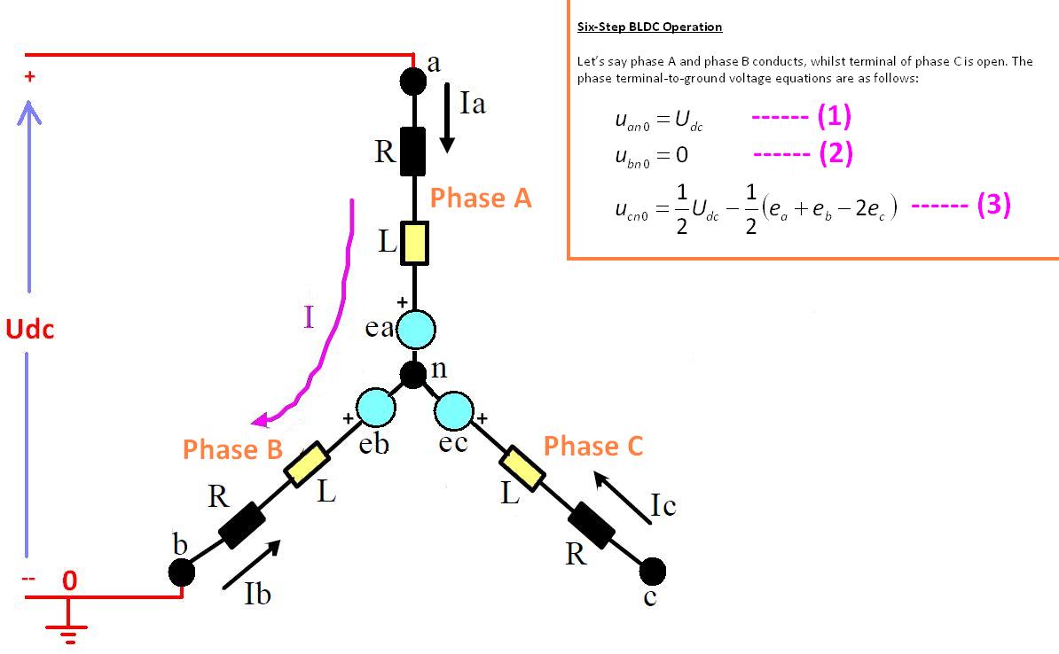
I wish to 'derive' the equations (1), (2), and (3) as shown in figure below by 'inspection' or 'observation'. Obviously, when phase C terminal is open, whilst phase A and phase B terminals are connected to positive DC link and negative DC link, respectively, phase A terminal-to-ground voltage, uan0 = Udc, and phase B terminal-to-ground voltage, ubn0 = 0. However, I am not able to 'derive' the equation (3) by just inspection... Could someone please advise?

Thanks


Unfortunately, I'm even unable to follow the first line. It can't be generally true, without additional assumptions about the involved e.m.f sources, I think.
 

    powersys

    Points: 2
    Helpful Answer Positive Rating
It is funny or incomplete or mismatch information. The equations can not be justified with the available information.
 

    powersys

    Points: 2
    Helpful Answer Positive Rating
FvM said:
Unfortunately, I'm even unable to follow the first line. It can't be generally true, without additional assumptions about the involved e.m.f sources, I think.

ark5230 said:
It is funny or incomplete or mismatch information. The equations can not be justified with the available information.

Sorry... Let's assume the 3-phase circuit is symmetrical (and sinusoidal), therefore, ea+eb+ec=0. Please advise.
 

I think the labelling is wrong. Uan is not equal to Udc. Ua = Udc Ub=0 Uc=float

Consider the neutral point voltage at n. The voltage at n can be stated in 3 ways relative to each phase.
Where phase A is connected to Udc, Un= Udc -RIa - L(dIa/dt) - ea.
Where Phase B is connected to ground Un= RIb + L(dIb/dt) + eb.
Where Phase C is unconnected Un=Uc + ec.

Ia=Ib=I so combining 1st and 2nd Un = 0.5*(Udc - ea + eb)
Also must have ea + eb + ec =0

So Uc = 0.5*(Udc - ea + eb) - ec

Added after 2 minutes:

Sorry got my eb and ec signs wrong.

Where phase A is connected to Udc, Un= Udc -RIa - L(dIa/dt) - ea.
Where Phase B is connected to ground Un= RIb + L(dIb/dt) - eb.
Where Phase C is unconnected Un=Uc - ec.

Ia=Ib=I so combining 1st and 2nd Un = 0.5*(Udc - ea + eb)
Also must have ea + eb + ec =0

So Uc = 0.5*(Udc - ea - eb) + ec
 

    powersys

    Points: 2
    Helpful Answer Positive Rating
Status
Not open for further replies.

Part and Inventory Search

Welcome to EDABoard.com

Sponsor

Back
Top