sammyt09
Newbie level 6
delta sigma modulation
Hi all,
I am having some problems with the verilogA simulation of a second order delta sigma modulator. I would be very greatful for any assistance.
I took the 'sigmadelta_1storder' cell from the Cadence 'ahdlLib' and modified it to be 2nd order. The resulting verilogA code is:
-------------------------------------------------------------------------------------
//
// Ideal 2nd order delta sigma ADC
//
`include "constants.vams"
`include "disciplines.vams"
module ADC_ideal(vin, vclk, vout);
input vin, vclk;
output vout;
electrical vin, vout, vclk ;
parameter real vth=0.0 ;
parameter real vout_high=1.8 ;
parameter real vtrans_clk=0.9 ;
parameter real trise=20n from (0:inf);
parameter real tfall=20n from (0:inf);
parameter real tdel=0.0 from [0:inf);
real vsum1, vsum2;
real vd;
real vint1, vint2;
real vout_val;
real hi, lo;
analog begin
@ ( initial_step ) begin
vout_val = 1.0;
hi=1.0;
lo=-1.0;
end
@ (cross(V(vclk)-vtrans_clk, 1.0))begin
// Difference 1
vsum1 = V(vin) - vd ;
// Integrator 1
vint1 = vsum1 + vint1;
// Difference 2
vsum2 = vint1 - vd ;
// Integrator 2
vint2 = vsum2 + vint2;
// Comparator
if (vint2 > vth)
vout_val = hi ;
else
vout_val = lo ;
// D2A
vd = vout_high * vout_val ;
end
V(vout) <+ transition(vout_val, tdel, trise, tfall);
end
endmodule
-------------------------------------------------------------------------------------
I then simulated the modulator using:
Vin = +/-1V sinusoid @ Fin = 200Hz
Fclk = 1MHz
Transient Analysis of 100ms
(The OSR is 512, but I have not yet considered the filter)
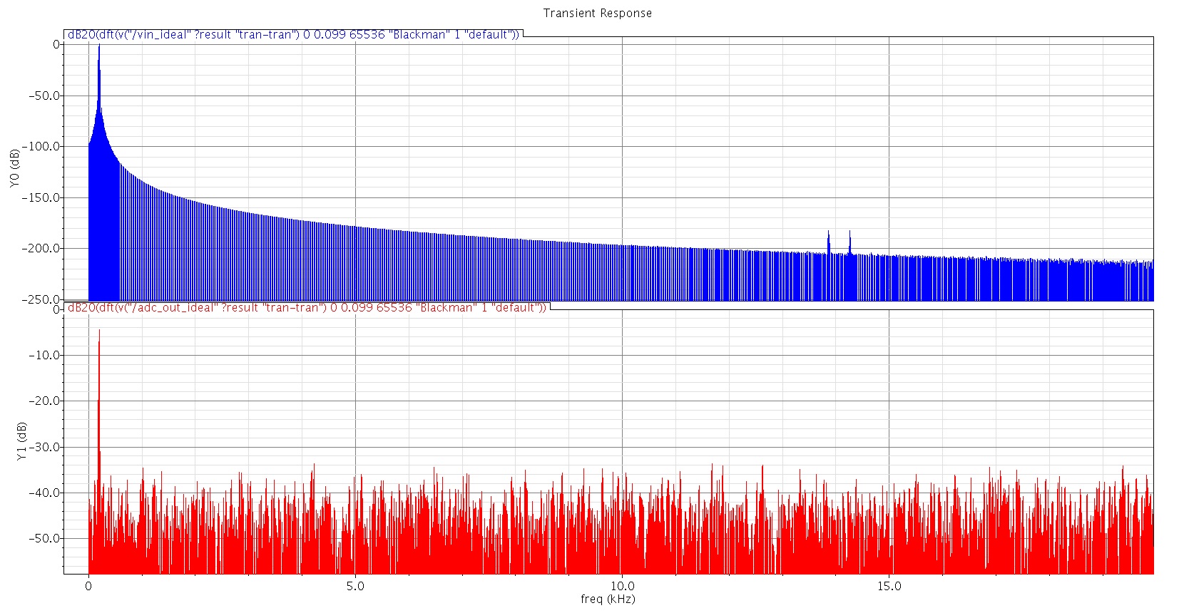
However, the performance appears to be very poor. It seems to "work", just not very well. As you can see from the attached plot below, the SNR of the output signal is less than 40dB. From my Matlab simulations, I believe an ideal modulator of this spec should result in a SNR of closer to 100dB.
So, I suppose I have a couple of questions:
1) Does anyone see a problem with the verilogA code I have provided? Is this correct for an ideal second order modulator?
2) Does anyone see an error with the method I am using to measure the SNR of the modulator output? As you can see from the plot, I performed a DFT over the 100ms adc output, using N=65536.
If anyone has any useful insights, it would be greatly appreciated. If you would like some more info regarding my setup, please ask.
Thanks in advance
Sammyt09
Hi all,
I am having some problems with the verilogA simulation of a second order delta sigma modulator. I would be very greatful for any assistance.
I took the 'sigmadelta_1storder' cell from the Cadence 'ahdlLib' and modified it to be 2nd order. The resulting verilogA code is:
-------------------------------------------------------------------------------------
//
// Ideal 2nd order delta sigma ADC
//
`include "constants.vams"
`include "disciplines.vams"
module ADC_ideal(vin, vclk, vout);
input vin, vclk;
output vout;
electrical vin, vout, vclk ;
parameter real vth=0.0 ;
parameter real vout_high=1.8 ;
parameter real vtrans_clk=0.9 ;
parameter real trise=20n from (0:inf);
parameter real tfall=20n from (0:inf);
parameter real tdel=0.0 from [0:inf);
real vsum1, vsum2;
real vd;
real vint1, vint2;
real vout_val;
real hi, lo;
analog begin
@ ( initial_step ) begin
vout_val = 1.0;
hi=1.0;
lo=-1.0;
end
@ (cross(V(vclk)-vtrans_clk, 1.0))begin
// Difference 1
vsum1 = V(vin) - vd ;
// Integrator 1
vint1 = vsum1 + vint1;
// Difference 2
vsum2 = vint1 - vd ;
// Integrator 2
vint2 = vsum2 + vint2;
// Comparator
if (vint2 > vth)
vout_val = hi ;
else
vout_val = lo ;
// D2A
vd = vout_high * vout_val ;
end
V(vout) <+ transition(vout_val, tdel, trise, tfall);
end
endmodule
-------------------------------------------------------------------------------------
I then simulated the modulator using:
Vin = +/-1V sinusoid @ Fin = 200Hz
Fclk = 1MHz
Transient Analysis of 100ms
(The OSR is 512, but I have not yet considered the filter)
However, the performance appears to be very poor. It seems to "work", just not very well. As you can see from the attached plot below, the SNR of the output signal is less than 40dB. From my Matlab simulations, I believe an ideal modulator of this spec should result in a SNR of closer to 100dB.
So, I suppose I have a couple of questions:
1) Does anyone see a problem with the verilogA code I have provided? Is this correct for an ideal second order modulator?
2) Does anyone see an error with the method I am using to measure the SNR of the modulator output? As you can see from the plot, I performed a DFT over the 100ms adc output, using N=65536.
If anyone has any useful insights, it would be greatly appreciated. If you would like some more info regarding my setup, please ask.
Thanks in advance
Sammyt09