yassin.kraouch
Advanced Member level 2
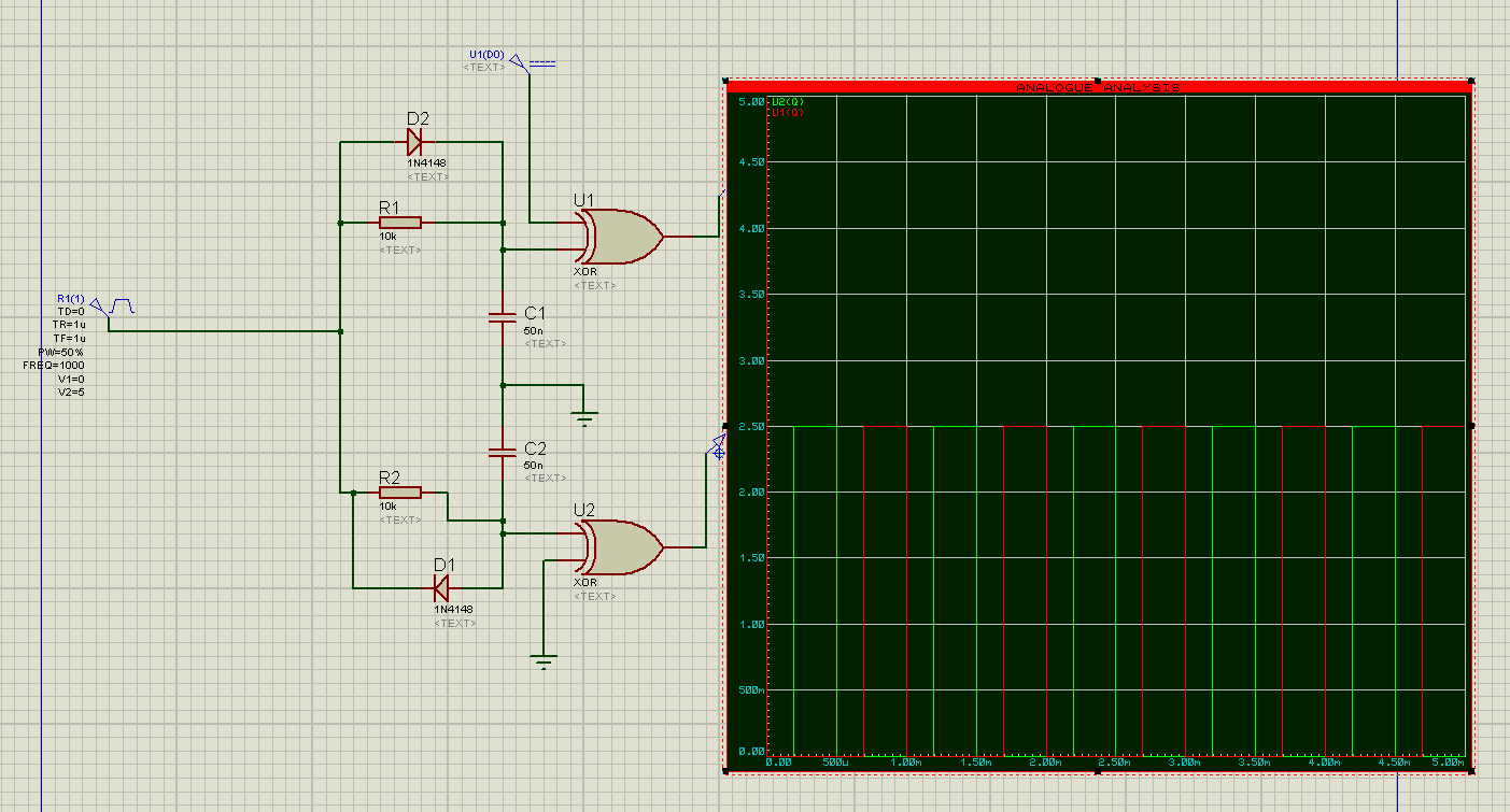
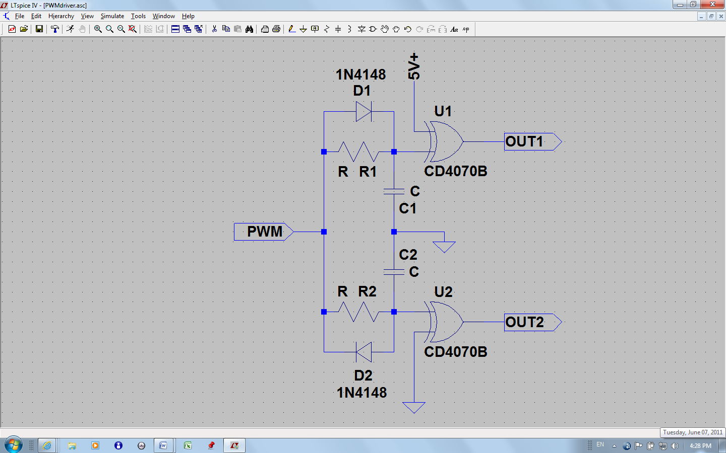
Hi, i have a microcontroller who output one PWM signal, i would like to drive two N-MOSFET as a switch, so the problem is with this PWM signal i like that the two signal are with dead time in order to drive the two mosfet and also inverted,
")