Continue to Site

Welcome to EDAboard.com

Welcome to our site! EDAboard.com is an international Electronics Discussion Forum focused on EDA software, circuits, schematics, books, theory, papers, asic, pld, 8051, DSP, Network, RF, Analog Design, PCB, Service Manuals... and a whole lot more! To participate you need to register. Registration is free. Click here to register now.

[SOLVED] Delay Circuit Vth Variation

Status
Not open for further replies.

vleam13

Member level 1
Joined
Mar 3, 2010
Messages
37
Helped
1
Reputation
2
Reaction score
1
Trophy points
1,288
Activity points
1,560
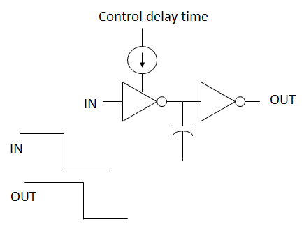
I am designing simple RC delay circuit with one cmos inverter + capacitor. The delay can be controlled by inverter current. Everything is ok but the delay variation is too big with vth variation. Any idea how to improve it?
 
Last edited:

I am afraid that it is natural for very simple circuits to be sensitive to some factors, mainly the temperature.

On the other hand, I guess the transient (rate of change) output voltage/current is not sharp when the input voltage is in the vicinity of Vth (at a specific temperature).

Your question is interesting but to answer it, one may need to write a book to cover all possible answers ;-)
 

Looks like it is not possible to improve by just tuning inverter size, inverter current or capacitor size....
Maybe new topology with vth compensation is needed.....
 

The main data that needs to be given to decide on a topology if not the final circuit, should define:

(1)
what is at the input(s); like the power supply voltage and the input signal as voltage/current with the equivalent impedance of its source.
(2)
what is at the output(s); like the voltage and current of the load in all possible states.
(3)
what is the relation(s) or function(s) between the input(s) and output(s).

So far, we know that the required function, as in (3), is a timer (though with no values for the minimum and maximum time).

On the other hand, sometimes one has a narrow list from which he can choose the circuit components.

So do you still have anything to add in order to find a good design while keeping it simple?

Kerim
 

23_1311406470.png


My circuit is as simple as this. But when vth changed, delay variation is too big.
 

Use a comparator instead of an inverter. You can then define precise thresholds and eliminate the errors you are seeing, which are inevitable with a simple inverter circuit.

Keith
 

Status
Not open for further replies.

Similar threads

Part and Inventory Search

Welcome to EDABoard.com

Sponsor

Back
Top