Continue to Site

Welcome to EDAboard.com

Welcome to our site! EDAboard.com is an international Electronics Discussion Forum focused on EDA software, circuits, schematics, books, theory, papers, asic, pld, 8051, DSP, Network, RF, Analog Design, PCB, Service Manuals... and a whole lot more! To participate you need to register. Registration is free. Click here to register now.

decrease in resonant frequency of dielectric coated wire antenna

Status
Not open for further replies.

ghasem_008

Full Member level 4
Joined
Feb 9, 2012
Messages
221
Helped
11
Reputation
22
Reaction score
10
Trophy points
1,298
Activity points
2,990
Hi.
why in a dielectric-coated cylindrical (metal) monopole antenna,increasing of dielectric thickness,decrease resonant frequency of antenna?
or why decrease bandwidth?
thanks
 

If you have a coaxial cable, you know the propagation speed is proportional to 1(rt(relative epsilon). So an electrically quarter wave piece of coaxial cable has a physical length of less then a quarter wave in air. For PE dielectric, propagation velocity is about 2e8 m/s (instead of 3e8 for air).

If you have an air filled coaxial cable that has a quarter wave resonant frequency at say 300 MHz (physical length 0.25 m), the resonant frequency goes down when adding the dielectric. In your case it is the same. Your vertical metallic bar is a transmission line (with radiation loss). As the electric field goes through the dielectric (like in the coaxial cable), the propagation velocity reduces.

The thicker the coating the more integral(E*ds) goes through the dielectric, the more the propagation velocity reduces. As most of the E-field goes through air, the propagation speed will not reduce equal as in a coaxial cable (where all integral(E*ds) goes through dieletric).

When using lossless dielectric, useful bandwidth goes down mostly. When adding lossy dielectric, bandwidth may increase, but radiation efficiency and gain go down.
 

thanks.
But your explanation is about propagation velocity .what is relation between your comment and bandwidth or resonant frequency?
my question is " "why" bandwidth and resonant frequency decrease?or equivalent,why electrical length increase with respect to when we don't have cover on wire antenna?
can you explain with more details?
 

When propagation velocity reduces, electrical length must reduce also to maintain the same resonant frequency, see relation below.

Lambda (wavelength) = (propagation velocity)/frequency

Your antenna behaves like a resonator (likely a quarter wave resonator). When you add loss (via lossy dielectric), the Q factor of the resonator reduces, hence the bandwidth increases. For a resonator:

BW(-3 dB impedance) = Fcenter/Q.

Besides the dielectric loss, there is the radiation loss (very desired in an antenna!). For antennas say < 0.6 lambda, reducing the length of the radiator, reduces the radiation loss. So when using a lossless dielectric the antenna length must decrease (lower propagation velocity), hence the loss reduces, and you get higher Q factor and less bandwidth.

It can be explained with mathematics in a more fundamental and solid way, but this requires at least good understanding of transmission line theory (as almost 90% is transmission line theory).
 

thanks.
as you know,in dielectric coated wire antenna,dielectric (cover) effect on the radiation characteristics can be presented by defining of this parameter:
P = [(epsd - 1)/epsd]*log(b/a)
where:
epsd = relative complex permitivity of dielectric cover
a = antenna radius
b-a = thickness of dielectric cover
can you explain why:
increasing the real part of "P" cause:
1- decrease peak input impedance
2- increase electrical length (decrease resonant frequency).
3- narrow bandwidth.
ALSO,why:
increasing the imaginary part of "P",cause:
1- increase peak input impedance
2- decrease electrical length (increase resonant frequency).
3-increase bandwidth
4-accentuates the power dissipated(decrease radiation efficiency)
5-accentuates the traveling wave component of current distribution.
I'm very gratefull...
ghasem
 

Though I do design antennas, I never encountered parameter "P"

Based on your formula I do have some Idea of what it can be, but what do you mean with "radiation characteristics"?

Your questions are too general now. It will result in a time consuming general answer that is very likely not useful for you. Try to narrow down your questions. I am sure many of the questions you have/had you can answer yourself if you understand transmission lines, field distribution around transmission, and transmission line resonators.
 

I'm sorry.you are right.my question is general.
P is a parameter that can be extracted from the proof of equations.(by moment method)


my mean from radiation characteristics is : gain,bandwidth,radiation efficiency and ...
actually,my expertise is in numerical methods and also I studied antenna & transmission lines,two years ago.
(if you have any question about numerical methods,I can help you)

can you explain these questions:
why increasing the real part of "P":
1- decrease peak input impedance
2- increase electrical length (decrease resonant frequency).
3- narrow bandwidth.

if you can,with transmission line theory give me a answer...
thank you very much...
 
Last edited:

To give you a solid mathematical explanation for the thin dielectric layer loss increase and reduction of propagation velocity (that means increase in electrical length), will take me some days.

By treating the round conductor as a coaxial transmission line with a virtual ground at around 0.125lambda you can calculate the effective complex dielectric constant (required for propagation velocity and loss) . Depending on the approximation you made (to keep the math doable), you may need some fudge factors to get better agreement between the simple approximation and real measurements. Once you have the transmission line properties of the dielectric coated wire, you can go back to transmission line theory to calculate impact in impedance and bandwidth of antennas.

I am not aware of public domain info, but it should be around. For example NEC4 (Numerical Electromagnetic Code, version 4) can handle dielectric covered wire and knowing the effect of dielectric coating on antenna properties (especially loss and required length reduction) is of interest for antenna design.
 

NO,I don't want to give me a mathematical explanation.

Can you give a qualitative explanation?why reduction of propagation velocity is equivalent with increase in electrical length?and why input impedance peak decrease?is there any qualitative explanation?
 

I allready tried to give you a qualitative explanation for lengh reduction because of the added dielectric, please read again my postings.

Regarding the peak impedance, I assume you mean half wave resonance impedance. I would recommend you to study the properties of the half wave resonator. It behaves as a parallel resonant circuit. Adding loss (due to dielectric) reduces the Q factor, hence the parallel equivalent resistance at resonance goes down.
 

I remember that in "how radius effect on bandwidh and input impedance of a monopole antenna?" topic,you said:

"Using Thick conductors results in more fringe field hence more virtual capacitance at the end of the monopole. This capacitance shifts the resonant frequency downwards. To compensate for this effect, you need to reduce the length."

while in ARRL antenna book we have:
"Larger diameter antenna wire lowers the wavelength at resonance. An antenna cut for ½ wave is actually less than ½ wave in electrical length due to using larger diameter wire. Therefore, for thicker wires the length of the antenna must be increased slightly."

I'm confused.finally larger diameter antenna deacrease or increase electrical length?

- - - Updated - - -

I can't understand why you say "electrical length" reduce due to dielectric cover,while in Balanis and ARRL antenna books,we have:
increasing the real part of "P" ,increase electrical length (decrease resonant frequency).
please clarify me...
 

"I'm confused.finally larger diameter antenna deacrease or increase electrical length?" increasing the diameter adds capacitance at the end of the radiatior, so the electrical length increases. You need to decrease the length the get the same resonant frequency again.

Adding dielectric increases the electrical length also, but this is because of adding the dielectric reduces the propagation velocity. So adding dielectric requires a shorter radiator.
 

in accordance with:
Lambda = velocity / frequency
when propagation velocity decrease, lambda decrease and therefore:
(Length/lambda) = electrical length =>increase.

OK!this problem solved.

Also,I know that:
increasing the diameter adds capacitance at the end of the radiatior.
Now,my question is:
Lateral edges of the dielectric does not affect the antenna?namely,we don't have a additional capacitance between metal antenna and dielectric edges (in dielectric medium)?so that input impedance change?

- - - Updated - - -

actually,in the in "how radius effect on bandwidh and input impedance of a monopole antenna?" topic,
you said:
"For quarter wave monopoles, the impedance slightly reduces with diameter"

while in ARRL antenna book,we have:

"The impedance at the resonant frequency increases slightly for larger diameter antenna wires"
Which one is correct?
thank you very much...
 

For quarter wave resonating monopoles over large ground plane, or half wave resonating dipoles, mine is correct: input impedance at resonance reduces slightly (put some in simulation and you will see, or build some and measure them).

A shorter radiator has less moving total charge given same input current. So the far field E-field strength reduces, hence total radiated power. Given certain feed current and less radiated power requires lower input impedance at resonance. You may know the theoretical half wave dipole has around 73 Ohms, but real world VHF/UHF half wave dipoles have lower resonant impedance, as they are physically less then a half wave in length.

Are you working on a thesis or school project? It would be good that you find some time to study the radiated field of an elementary current segment, how a far field radiation pattern is formed (that is: addition of contributions from current segments), and total radiated power. It will help you to dive deeper in into the nice world of antennas.

I don't understand the "lateral edges" point.
 
thank you very much for your attention.yes,this is a project.of course,main section of my project is simulation and I want to prepare some theoretical explanations.
where can I find a english translation from your attachment (**broken link removed**

Also,One question has occupied my mind.

Lateral edges of the dielectric does not affect the antenna?namely,we don't have a additional capacitance between metal antenna and dielectric edges (in dielectric medium)?so that input impedance change?
 

Can you elaborate the "lateral edges" question, as I don't understand it (a picture may help)?

I'm sorry, I don't have a good translation of the monopole document. I can PM you a translation done by another radio amateur, but this has not been verified by me. The monopole document does not give the full math behind everything as it is mainly intended for radio amateurs.
 

yes,of course.
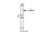
please look at the following picture:
dielectric coated wire antenna.png
I think that there is a additional capacitance between wire antenna edge and dielectric medium.
are you agree?
can you send me your translation?Im very gratefull...
 

This is the capacitance that slows down the propagation speed as part of integral(E*ds) goes through this dielectric. The thicker the layer, the larger part of integral(E*ds) goes through it and the larger the effective dielectric constant of the dielectric coating. See also posting #2.
 

yes,this is true.
But in a IEEE paper from it's simulations,I saw that in a thicker antenna,resonant length decrease:sad:
what is relation between capacitance at the end of the radiatior and electrical length (you said in posting#12 that increasing the diameter adds capacitance at the end of the radiatior, so the electrical length increases).
 

wimRFP.I have a question.
what is equivalent circuit of a dielectric resonator antenna?
in metal cylindrical antenna we have a inductance due to it's arms.SO equivalent circuit is a series RLC circuit.But in a dielectric resonator antenna what is happening?
 

Status
Not open for further replies.

Part and Inventory Search

Welcome to EDABoard.com

Sponsor

Back
Top