maark6000
Member level 5
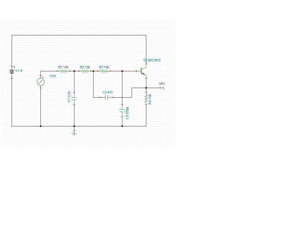
hello all, i have some questions about the attached schematic. I believe this is a low pass filter, it comes from an old guitar foot-pedal schematic.
my question relates to how to calculate the critical frequency for this circuit. I know how to compute it for an RC filter... fc=(1 / 2pi*R*C). After the AC source the first R / C (10k / 2.2n), we would expect a Fc of 7234.3 Hz. However, I don't know what to make of the next part, another 10k but this time with the larger cap tied to the emitter. Nor do I know why you have yet another R / C component following that... with it's small 330 pF value it's critical frequency is way up at 48kHz, a frequency I thought would have been taken care of by the first R/C element.
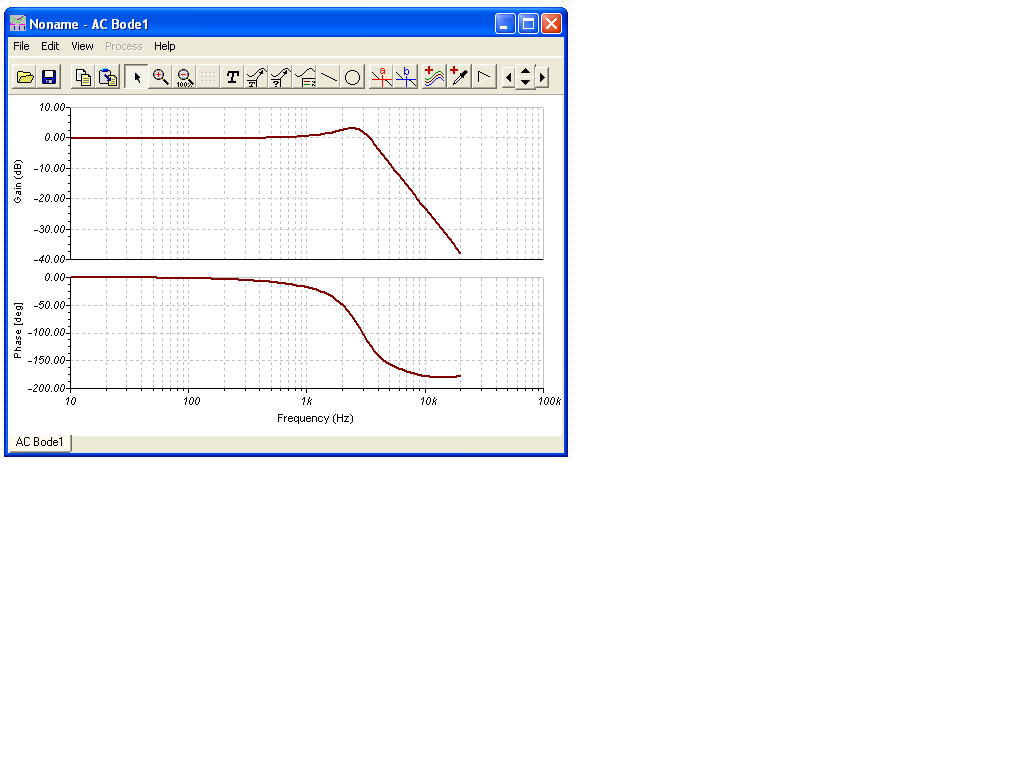
One important word about this schematic... the AC source is about 1 V, but is biased up +2.84 V. My simulations suggest that the transistor would be forward conducting. the base voltage ends up being 2.83 V, the emitter voltage 2.15 V (simulated) and another thing to be aware of, the "battery" voltage is 8 volts, not 18 like it looks on the schematic (drawn in TinaTI). I've included the AC analysis of it, it seems to have a sharp drop off after the -3db point at around 3.9 kHz.
Any and all mathy explanations welcomed. Thank you in advance.
my question relates to how to calculate the critical frequency for this circuit. I know how to compute it for an RC filter... fc=(1 / 2pi*R*C). After the AC source the first R / C (10k / 2.2n), we would expect a Fc of 7234.3 Hz. However, I don't know what to make of the next part, another 10k but this time with the larger cap tied to the emitter. Nor do I know why you have yet another R / C component following that... with it's small 330 pF value it's critical frequency is way up at 48kHz, a frequency I thought would have been taken care of by the first R/C element.
One important word about this schematic... the AC source is about 1 V, but is biased up +2.84 V. My simulations suggest that the transistor would be forward conducting. the base voltage ends up being 2.83 V, the emitter voltage 2.15 V (simulated) and another thing to be aware of, the "battery" voltage is 8 volts, not 18 like it looks on the schematic (drawn in TinaTI). I've included the AC analysis of it, it seems to have a sharp drop off after the -3db point at around 3.9 kHz.
Any and all mathy explanations welcomed. Thank you in advance.