Continue to Site

Welcome to EDAboard.com

Welcome to our site! EDAboard.com is an international Electronics Discussion Forum focused on EDA software, circuits, schematics, books, theory, papers, asic, pld, 8051, DSP, Network, RF, Analog Design, PCB, Service Manuals... and a whole lot more! To participate you need to register. Registration is free. Click here to register now.

[SOLVED] Decimation Filter in Verilog - can I use Blocking assignment

Status
Not open for further replies.

jdp721

Member level 2
Joined
Jun 29, 2009
Messages
45
Helped
4
Reputation
8
Reaction score
3
Trophy points
1,288
Activity points
1,621
Hi,

I am trying to realize a CIC decimation filter (for delta-sigma ADC) in Verilog.

I want to know whether to use NON-BLOCKING ASSIGNMENT <= or BLOCKING ASSIGNMENT = in Verilog implementation of the constituent integrators and differentiators.

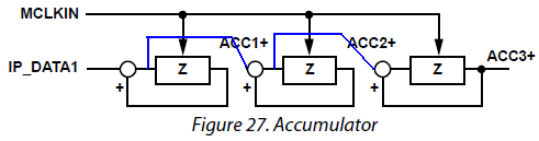
E.g., for the integrator section (image below), commonly cited code is like:
acc.PNG

always @ (posedge clk_in)
begin /*perform accumulation process*/
acc1 <= acc1 + ip_data;
acc2 <= acc2 + acc1;
acc3 <= acc3 + acc2;
end


I want to know if I can use Blocking assignment = instead of <= above - shouldn't that be better?
 

You need to read about blocking and non-blocking assignments...

If you want to describe a Flip-flop (register) then you need to use non-blocking assignments (i.e. assignments inside the always @ (posedge clk) block).

Using blocking assignments in this case means you are trying to force all the computations to occur in sequential order in the current clock cycle (i.e. not pipelining, but combinationally). With the added feedback of the output of each acc# to itself I'm not entirely sure what that would result in modeling.

Verilog is NOT software, it's a hardware description language, if you don't know what the hardware should look like then you need to know that before you write Verilog to describe it.
 
  • Like
Reactions: jdp721

    jdp721

    Points: 2
    Helpful Answer Positive Rating
I want to know if I can use Blocking assignment = instead of <= above - shouldn't that be better?
Apart from the problem explained by ads-ee. why do you think the blocking variant should be better? It replaces the regular CIC integrator part by a different circuit. It reduces the propagation delay by two clock cycles at cost of maximum design speed. But there's no reason to do so.

6421507600_1427819090.png
 
  • Like
Reactions: jdp721

    jdp721

    Points: 2
    Helpful Answer Positive Rating
THANK YOU ads-ee for the nice detail explanation; and FvM for drawing the diagram for explaining it to me :smile:

Indeed, my reason for arguing for Blocking assignment was to reduce delay (both in the integrator and differentiator sections of the CIC decimation filter) - like the o/p of each section will be generated in a single clock cycle itself for a given i/p...when we use something like:

always @ (posedge clk_in)
begin /*perform accumulation process*/
acc1 = acc1 + ip_data;
acc2 = acc2 + acc1;
acc3 = acc3 + acc2;
end


FvM, can you please tell a little more on what you meant by saying "...at cost of maximum design speed"?
 

FvM, can you please tell a little more on what you meant by saying "...at cost of maximum design speed"?
ads-ee explained the reason
Using blocking assignments in this case means you are trying to force all the computations to occur in sequential order in the current clock cycle (i.e. not pipelining, but combinationally).
If you follow the modified signal flow, you see three cascaded add operations that have to be carried out in a single clock cycle. Results in roughly 1/3 of maximum design speed.
 
  • Like
Reactions: jdp721

    jdp721

    Points: 2
    Helpful Answer Positive Rating
Regardless I still don't think it would work correctly as there has to be storage for acc1 and acc2 as they are feed back to the input side of their respective assignments. Making accumulators in combinational logic means you have to implement latches as you must break the combinational loop somehow.
 
  • Like
Reactions: jdp721

    jdp721

    Points: 2
    Helpful Answer Positive Rating
I believe the code works as decimator, It will infer FFs for acc1, acc2 and acc3, also if blocking assignments are used.

This happens because previous values are used in each assigment and it's under control of an edge sensitive condition.
 
  • Like
Reactions: jdp721

    jdp721

    Points: 2
    Helpful Answer Positive Rating
I believe the code works as decimator, It will infer FFs for acc1, acc2 and acc3, also if blocking assignments are used.
This happens because previous values are used in each assigment and it's under control of an edge sensitive condition.

So, with blocking-assignments, the realization will be like:

the previous values of acc1, acc2 and acc3 will remain stored in FFs, and those values (along with ip_data) will be used by a combinational ckt to compute new values of acc1, acc2 and acc3.

This will reduce the clock rate somewhat, but won't that be a more realistic implementation of the cascaded integrators/differentiators than the pipelined version, like will the o/p be same (maybe, delayed) from the two realizations....I might be very naive in asking this, so pls don't mind. :)

BTW, thank you to FvM and ads-ee once again for being so helpful :smile:
 

I really don't know what a "realistic implementation" is meaned to be. Digital signal processing is using pipelining (and non-blocking assignments) as far as possible, mainly due to timing requirements but also more straightforward synthesis.

There are a few cases were blocking statements are needed, I don't see why CIC should be among it.
 

Thanks FvM and ads-ee for the clarification and help.

Please have my reagrds,
Jdp.
 

There are a few cases were blocking statements are needed, I don't see why CIC should be among it.
I'd really like to see a place where Verilog blocking assignments are needed (required) in an edge sensitive always block, that couldn't be coded using either a continuous assign statement or a combinational always block.

I have problems with code that infers registers where the blocking assignments are dictating it should be handled as combinational logic. Doing this relies heavily on the quality of the synthesis tools and the simulator, which may not match in their results.
 
  • Like
Reactions: jdp721

    jdp721

    Points: 2
    Helpful Answer Positive Rating
Status
Not open for further replies.

Part and Inventory Search

Welcome to EDABoard.com

Sponsor

Back
Top