harvie
Full Member level 1

- Joined
- Sep 10, 2014
- Messages
- 98
- Helped
- 2
- Reputation
- 4
- Reaction score
- 2
- Trophy points
- 1,288
- Location
- Prague
- Activity points
- 2,486
Hello,
i am trying to design constant current step-down SMPS with following parameters
+ 0-10A (maybe 20A) set by pot
+ very cheap
+ minimal number of components (eg: LM358, N-MOSFET, zener diode, few passives)
+ very inprecise (i don't care about +-0.5A ripple)
+ voltages up to 18V (or determined by used opamp)
+ should survive short circuit (= should limit current regardless of load)
+ should be cheap4ss circuit for electrolysis experiments and similar, controlling resistive wire heater, eventually charging old automotive batteries, nothing serious
+ think of this as of joule thief kind of circuit, JUST NOTHING SERIOUS. really.
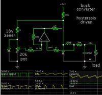
I am playing with this simplified circuit i've created in falstad simulator, however i don't know how to properly calculate values:

How i suppose it to work:
On the upper-right part of schematic you can see traditional step-down topology with N-channel MOSFET and terminals for attaching load probably with some ripple rejection capacitors which are missing at image.
Step-down circuit is in series with shunt resistor with parallel capacitor which should smooth out the voltage readings on shunt and keep whole thing running at frequency reasonable for opamps and MOSFET. Shunt is selected to have reasonably low resistance, so there will not be much of loss.
Shunt voltage is then compared using comparator with reference voltage made using zener diode with proper current limiting resistor or 7805, etc... then there is resistive divider which lowers the reference voltage to something more similar to what we can sense on shunt.
Comparator is followed by schmitt trigger to ensure proper saturation of MOSFET which follows. and reduce unwanted oscillations.
So when cicuit is powered on, the shunt voltage rises over reference voltage (as shunt capacitor charges), which makes it to close MOSFET, therefore shunt voltage drops (as shunt capacitor discharges), which makes MOSFET open and everything repeats again. I hope this will reach some kind of balanced state which will hopefully provide +- constant current with possibility of seting it using potentiometer and ampermeter. Current doesn't even have to be predictable, but it should have +- stable RMS as long as you don't turn the pot.
Do you think that this can work? How should i choose proper inductor? Can you help me with some basic mathematics behind this circuit?
PS: i know that this can be done with specialized ICs like LM2596 using external error amplifiers used to fool CV feedback inputs. i know that there are cheap4ss linear solutions using LM317. and this is NOT my homework for school. i am just trying to rethink that concept. i want to find some poor man's high current regulator design. I saw simple 20A current regulators on the web, however they are not suitable for short circuits as there is no choke. especially "HHO fringe scientists" are using these kind of circuits.
i am trying to design constant current step-down SMPS with following parameters
+ 0-10A (maybe 20A) set by pot
+ very cheap
+ minimal number of components (eg: LM358, N-MOSFET, zener diode, few passives)
+ very inprecise (i don't care about +-0.5A ripple)
+ voltages up to 18V (or determined by used opamp)
+ should survive short circuit (= should limit current regardless of load)
+ should be cheap4ss circuit for electrolysis experiments and similar, controlling resistive wire heater, eventually charging old automotive batteries, nothing serious
+ think of this as of joule thief kind of circuit, JUST NOTHING SERIOUS. really.
I am playing with this simplified circuit i've created in falstad simulator, however i don't know how to properly calculate values:

How i suppose it to work:
On the upper-right part of schematic you can see traditional step-down topology with N-channel MOSFET and terminals for attaching load probably with some ripple rejection capacitors which are missing at image.
Step-down circuit is in series with shunt resistor with parallel capacitor which should smooth out the voltage readings on shunt and keep whole thing running at frequency reasonable for opamps and MOSFET. Shunt is selected to have reasonably low resistance, so there will not be much of loss.
Shunt voltage is then compared using comparator with reference voltage made using zener diode with proper current limiting resistor or 7805, etc... then there is resistive divider which lowers the reference voltage to something more similar to what we can sense on shunt.
Comparator is followed by schmitt trigger to ensure proper saturation of MOSFET which follows. and reduce unwanted oscillations.
So when cicuit is powered on, the shunt voltage rises over reference voltage (as shunt capacitor charges), which makes it to close MOSFET, therefore shunt voltage drops (as shunt capacitor discharges), which makes MOSFET open and everything repeats again. I hope this will reach some kind of balanced state which will hopefully provide +- constant current with possibility of seting it using potentiometer and ampermeter. Current doesn't even have to be predictable, but it should have +- stable RMS as long as you don't turn the pot.
Do you think that this can work? How should i choose proper inductor? Can you help me with some basic mathematics behind this circuit?
PS: i know that this can be done with specialized ICs like LM2596 using external error amplifiers used to fool CV feedback inputs. i know that there are cheap4ss linear solutions using LM317. and this is NOT my homework for school. i am just trying to rethink that concept. i want to find some poor man's high current regulator design. I saw simple 20A current regulators on the web, however they are not suitable for short circuits as there is no choke. especially "HHO fringe scientists" are using these kind of circuits.
Last edited:


