jk1204
Newbie level 4
hi
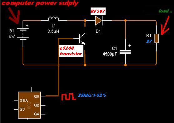
i am trying to make dc_dc boost converter...vin 5v(old compurt power supply) vout 20v...load 27ohm.....i have 3.3u inductor 15a & 28a saturation ...transistor c5200.. Diode RF307
the problem is i cant reach above 11v. with 33khz reach 11.4v@16% duty and then the voltage fall when duty more than 16%...i had tried different freq 27khz...55khz..atc.. the highest voltage i reached 11.5 then the voltage start to fall when increasing the duty
what the problem?